

Description
Hard-Numbers: Technical Specifications
-
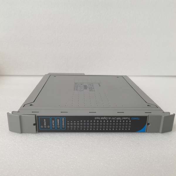
Input Channels: 40 TMR digital inputs (triplicated circuits per channel)
-
Input Voltage Range: -6V to +36V DC (measurement range); 18-30V DC operating
-
Nominal Input: 24V DC (sink/source configurable)
-
Input Impedance: 5 kΩ
-
Thresholds: User-configurable per channel
-
Safety Accuracy: ±0.5V DC
-
Maximum Withstanding: ±50V DC
-
Isolation: 2500V RMS impulse withstand (opto/galvanic); 50V reinforced continuous isolation
-
Measurement Method: Sigma-delta input circuit with triplicated voltage measurement
-
Voting Architecture: 2-out-of-3 (2oo3) voting on input data
-
Diagnostic Coverage: >99% (IEC 61508 SIL 3)
-
Sequence of Events (SOE): 1 ms resolution; ±10 ms timestamp accuracy
-
Line Monitoring: Open circuit and short circuit detection (per-channel configurable)
-
Power Consumption: 20W typical; 29W maximum dissipation
-
Backplane Supply: 20-32V DC (IMB – Inter-Module Bus)
-
Operating Temperature: 0°C to +60°C (standard); -20°C to +60°C (some variants)
-
Storage Temperature: -25°C to +70°C
-
Humidity: 10% to 95% RH non-condensing
-
Dimensions: 266 mm × 31 mm × 303 mm (H × W × D)
-
Weight: 1.18 kg (2.6 lb)
-
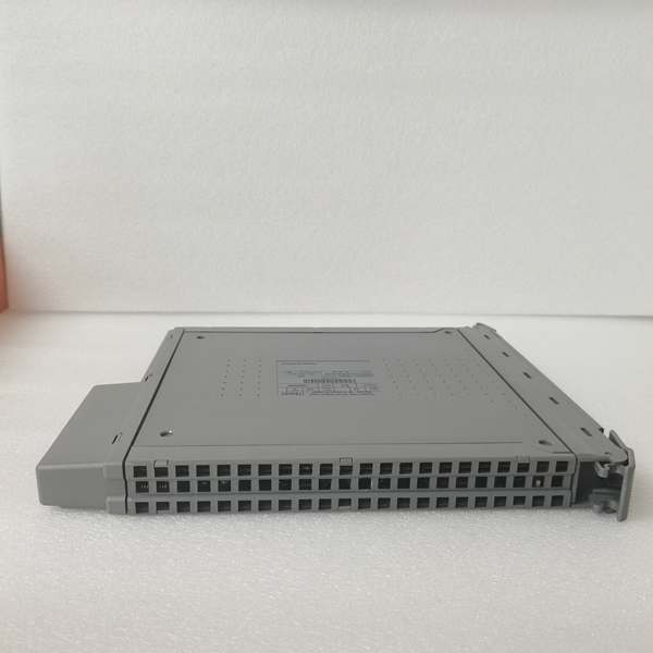
Mounting: T8100/T8300 I/O module slot
-
Hot Swap: Yes (Companion or SmartSlot configuration)
-
Certifications: TÜV SIL 3 (IEC 61508), CE, ATEX

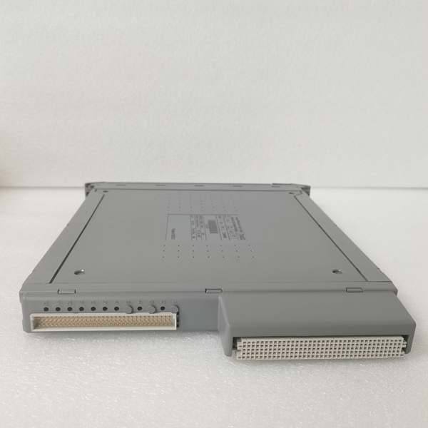
ICS TRIPLEX T8403C
The Real-World Problem It Solves
Safety instrumented systems cannot tolerate false trips or missed trips—either costs millions in lost production or risks catastrophic failure. Traditional single-channel digital inputs provide no diagnostic coverage; a shorted wire or failed input circuit goes undetected until it’s too late. The T8403C puts three independent input circuits on every channel, voting the results in real-time. If one circuit drifts or fails, the other two maintain safe operation while flagging the fault for repair.
Where you’ll typically find it:
-
Emergency shutdown (ESD) pushbuttons and limit switches on oil & gas platforms
-
Fire and gas detector inputs in offshore platform safety systems
-
Burner management flame scanner inputs in power plant boilers
This module eliminates the “single point of failure” in safety loops while providing 1ms event recording for post-trip analysis—critical for proving compliance and tracing root causes.
Hardware Architecture & Under-the-Hood Logic
The T8403C functions as a safety-critical input conditioner—not merely passing digital states, but measuring analog voltage levels with three independent sigma-delta converters and voting the results.
Signal flow and processing logic:
-
Triplicated Inputs: Each of the 40 channels connects to three identical input circuits (A, B, C). Each circuit includes signal conditioning, 5kΩ input impedance, and isolation barriers.
-
Sigma-Delta Conversion: Three independent sigma-delta A/D converters measure the field voltage on each channel. This provides both digital state determination (on/off) and analog health monitoring (voltage level diagnostics).
-
2oo3 Voting: A dedicated voter circuit compares the three measurements. If all three agree, that state passes to the IMB. If one disagrees, the voter masks the faulted channel and flags a diagnostic alarm—no trip occurs unless two channels agree on the dangerous state.
-
Line Monitoring: When enabled, the module sources a small current to detect open circuits (broken wires) and short circuits (shorted field wiring). This catches field faults that could prevent a trip when needed.
-
SOE Recording: A 1ms-resolution timestamp latches on any state change, regardless of scan rate. This goes to the TMR Processor for sequence reconstruction during incident analysis.
-
IMB Interface: The Inter-Module Bus connects to the Trusted TMR Processor (T8110/T8151B), providing power and high-speed communication. The module reports channel states, diagnostic status, and SOE data continuously.
ICS TRIPLEX T8403C
Field Service Pitfalls: What Rookies Get Wrong
Assuming “Digital Input” Means Simple On/Off
The T8403C measures analog voltage levels, not just digital states. If the field device supplies 18V instead of 24V due to cable resistance or power supply sag, the module may flag a “low voltage” diagnostic or fail to register the input—depending on threshold settings.
-
Field Rule: Check the configured voltage thresholds in the Trusted Toolset before blaming the module. Default thresholds are typically 15V ON / 5V OFF, but these are user-configurable per channel. Measure field voltage at the module terminals under load; a 24V supply showing 19V at the T8403C indicates a wiring problem, not a module fault.
Enabling Line Monitoring Without Understanding the Load
Line monitoring requires a minimum load current to distinguish between open circuit and valid OFF state. If the field device has high impedance or the cable capacitance is excessive, the module may false-alarm “open circuit” when the switch is actually closed.
-
Quick Fix: Disable line monitoring for that channel if the field device cannot sink the required current (typically 2-3mA). Alternatively, install a bleeder resistor across the field contacts to provide load current. Document this in the cause-and-effect matrix—future techs will assume line monitoring is active everywhere if you don’t note the exceptions.
Mixing T8403 and T8403C in the Same Chassis
The T8403C is a later revision (SerC) with enhanced diagnostics and potentially different timing characteristics. While backwards-compatible in most configurations, mixing revisions in a TMR system can cause subtle diagnostic disagreements during fast transients.
-
Field Rule: When replacing a failed T8403, use the same revision level if possible. If upgrading to T8403C, replace all three channels of a redundant safety function simultaneously to ensure matched response times. Check the “SerC VerO44” label—earlier revisions lack some SOE buffering features.


