
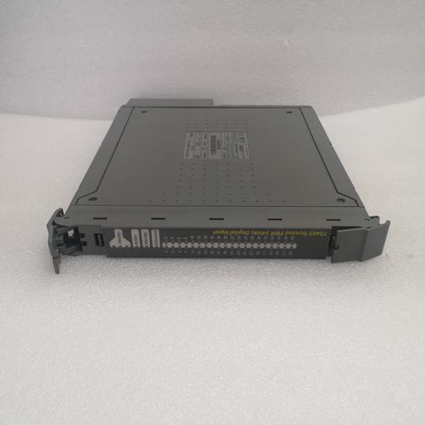
Description
Hard-Numbers: Technical Specifications
-
Protocol Support: TriStation 1131, Trusted Inter-Module Bus (IMB), Modbus TCP/IP (via system integration)
-
Input Channels: 40 TMR digital inputs (5 isolated groups × 8 channels each)
-
Input Voltage Range: 19.2 Vdc to 30 Vdc (24 Vdc nominal)
-
Input Current: 7 mA typical at 24 Vdc
-
Input Type: Sinking (current sinking to field common)
-
Threshold Configuration: User-configurable per channel (default 15V ON / 5V OFF)
-
Sigma-Delta Resolution: 12-bit effective voltage measurement
-
Line Monitoring: Open circuit and short circuit detection (requires external line monitoring device)
-
Isolation Rating: 2500 V impulse withstand, 500 Vac continuous (channel to system logic), 50V reinforced between groups
-
SOE Resolution: 1 ms timestamp accuracy
-
SOE Buffer: 1000 events onboard, transferable to 4000-event CI buffer
-
Digital Filtering: Configurable 50/60 Hz noise rejection
-
Operating Temperature: 0°C to +60°C (standard), -40°C to +70°C (extended variants)
-
Power Dissipation: 10 W typical
-
Hot-Swap: Supported via Companion Slot or SmartSlot configuration
-
Safety Certification: TÜV IEC 61508 SIL 3

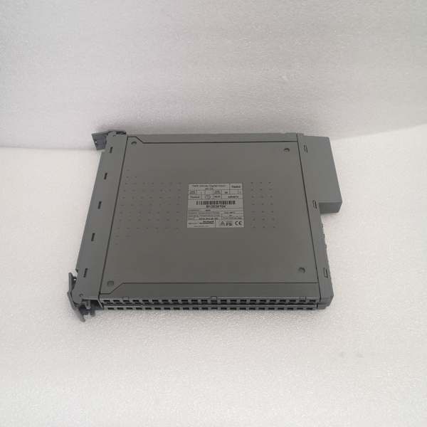
ICS Triplex T8403
The Real-World Problem It Solves
A welded contact or broken wire in a safety loop can lie dormant for months until it’s too late—either failing to trigger when needed or causing a spurious trip that costs millions. The T8403 eliminates this “silent failure” nightmare by measuring actual field voltage with sigma-delta precision and offering per-channel line monitoring to detect opens and shorts before they become dangerous. It doesn’t just read contacts; it interrogates the wiring integrity continuously.
Where you’ll typically find it:
-
Emergency shutdown pushbutton and limit switch monitoring in refinery process units
-
Fire & gas detector contact interfaces on offshore platforms
-
Turbine overspeed protection and auxiliary trip relay monitoring in power generation
This module tells you if your safety wiring is healthy, not just whether the switch is open or closed—no more guessing about field circuit integrity.
Hardware Architecture & Under-the-Hood Logic
The T8403 isn’t a simple opto-isolator card—it’s a distributed measurement system with three independent analog-to-digital converters per channel. Each field input is wired to three separate sigma-delta ADC circuits that measure actual voltage levels, not just on/off states. The module performs 2oo3 voting on the voltage measurements themselves, not just binary logic states, allowing it to detect drift and degradation before they become hard failures.
Internal Signal Flow:
-
Field Signal Triplication: Each of the 40 field inputs connects to three independent input circuits (A, B, C channels) with individual signal conditioning and isolation barriers
-
Sigma-Delta Conversion: Each channel’s ADC samples field voltage at high resolution, converting analog levels to digital values with 12-bit precision
-
Threshold Comparison: Each voted voltage measurement is compared against user-configurable ON/OFF thresholds (default 15V/5V) to determine the logical state
-
Line Monitoring Logic: When enabled, the module sources a small test current to detect open circuits (infinite impedance) or short circuits (zero impedance) in field wiring
-
2oo3 Voting: The three channel processors exchange measurement data via the IMB; if one ADC reads differently, the other two out-vote it and flag the discrepancy
-
SOE Timestamping: State changes trigger 1ms-resolution timestamps stored in the onboard buffer for sequence-of-events analysis
ICS Triplex T8403
Field Service Pitfalls: What Rookies Get Wrong
Assuming Line Monitoring Works Without External Components
Engineers enable line monitoring in TriStation and expect the module to magically detect broken wires. It can’t. The T8403 requires an external line monitoring device (typically a resistor network or specialized termination assembly) installed at the field switch to create the current loop necessary for open/short detection.
-
Field Rule: Verify the T8800 Field Termination Assembly (FTA) or equivalent line monitoring hardware is installed at the field device before enabling diagnostics. Without it, you’ll get false “open circuit” alarms on every channel. Check the wiring diagram—there should be a 22kΩ pull-up or similar termination at the switch.
Ignoring the 7mA Input Current Reality
The module sinks 7mA per active input. On a 40-channel card with all inputs energized, that’s 280mA just for input current. Rookies size the field power supply for the logic only and forget the input burden, causing voltage sag and intermittent “brownout” faults on high-impedance sources.
-
Quick Fix: Calculate total load: (Number of active inputs × 7mA) + (line monitoring current if enabled). Size your 24V field supply for 125% of this load. Measure field voltage at the module terminals under full load—if it drops below 19.2Vdc, you’ll get threshold violations. Use heavier gauge wire (14 AWG minimum) for long field runs to minimize IR drop.
Configuring All Channels with Default Thresholds in Noisy Environments
The default 15V ON / 5V OFF thresholds work fine in clean control rooms, but in motor starter buckets or solenoid valve manifolds with 60Hz ground noise, you’ll get chatter and false transitions. Rookies don’t adjust the hysteresis or enable the 50/60Hz filter, then blame the module for “glitchy” inputs.
-
Field Rule: In high-noise environments, widen the thresholds (e.g., 18V ON / 3V OFF) and enable the digital filter in TriStation 1131 configuration. Check the “Field Voltage” diagnostic register—if you’re seeing 2-3V of AC ripple superimposed on the DC level, you’ve got ground loop issues. Fix the shield grounding (single-point ground at the T8403 end only) before adjusting thresholds, or you’re masking a wiring problem.


