
Description
Key Technical Specifications
| Parameter | Details |
|---|---|
| Manufacturer | ICS Triplex (affiliated to Rockwell Automation) |
| Power Supply | Dual 24VDC diode ored, also adaptable to 18 – 32VDC |
| Power Consumption | Maximum 1.7W, featuring low energy consumption |
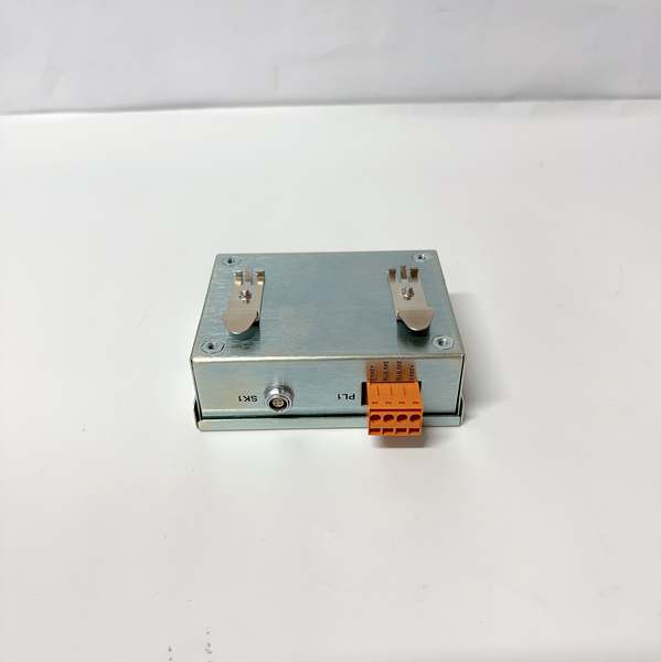
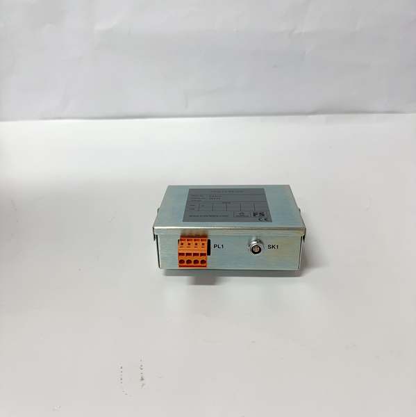
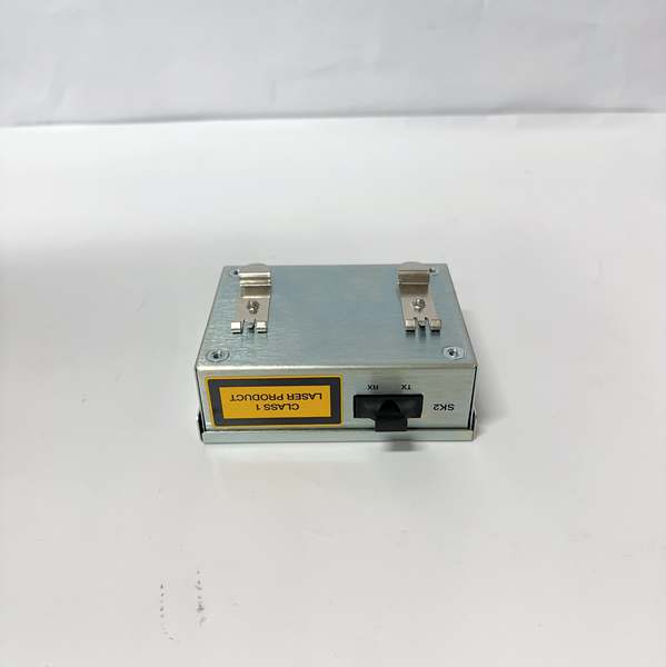
| Fiber – related Parameters | Supports singlemode/multimode fiber; operating wavelength of 1310nm/1550nm; equipped with SC – type connectors for two fibers (Tx and Rx). The minimum transmitter power is -15dBm, and the receiver sensitivity is -28dBm |
| Transmission Performance | Maximum communication distance can reach 10km; maximum propagation time difference is 80ns; maximum fiber length difference is 15m |
| Environmental Adaptability | Operating temperature ranges from 0°C to 60°C (some sources indicate it can withstand -40°C to 70°C for harsher industrial environments); non – operating temperature is -25°C to 70°C; works in 10% – 95% RH non – condensing humidity |
| Physical Specifications | Dimensions are 84mm×110mm×40mm; weight is about 320g (some versions are 1.2kg); adopts DIN rail mounting |
| Auxiliary Functions | Equipped with Link and Activity LED indicators for real – time monitoring of communication status; MTBF reaches 150,000 hours |
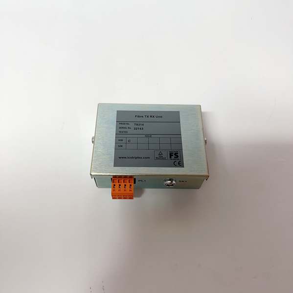
ICS Triplex T8314
Field Application & Problem Solved
In large – scale industrial fields such as oil and gas, chemical engineering, and power generation, long – distance data transmission between remote equipment and the central control system often faces multiple challenges. Conventional copper wire communication is prone to electromagnetic interference from high – voltage equipment and variable frequency drives on site, resulting in distorted or lost data. Moreover, its transmission distance is limited, which cannot meet the needs of large – scale industrial parks or cross – area equipment connection. In addition, sudden power failures or single – path communication faults may lead to interrupted control signals, endangering the safety of critical production processes.
The T8314 well addresses these pain points. In offshore drilling platforms, it realizes data transmission between underwater sensor equipment and the on – board central control room. Its 10km long – distance transmission capability and anti – corrosion design can resist the harsh marine environment of salt spray. In large chemical plants, it connects the control modules of scattered reaction workshops and the central SIS system. The fiber optic transmission method gives it strong immunity to electromagnetic interference, ensuring the accurate transmission of signals such as reactor temperature and pressure. In thermal power plants, its dual power supply design ensures that even if one power supply path fails, the module can still operate stably, avoiding shutdown accidents caused by communication interruption during power generation.
Its core value lies in two aspects. On one hand, fiber optic transmission not only breaks the distance limit of traditional copper wire communication but also fundamentally solves the problem of electromagnetic interference in industrial sites, ensuring data integrity. On the other hand, its redundant power supply and high MTBF design greatly reduce the probability of module failure, providing a reliable communication guarantee for the continuous operation of industrial systems without the need for frequent maintenance and replacement.
Installation & Maintenance Pitfalls (Expert Tips)
- Avoid Random Selection of Fiber Types: A common mistake during installation is mismatching the fiber type with the module’s requirements. If multimode fiber is used when the module is configured for long – distance transmission with singlemode fiber, the signal will attenuate sharply beyond a short distance, leading to communication failure. Before installation, confirm whether the module is set for singlemode or multimode operation and select the corresponding fiber. When cutting the fiber, use a professional cleaver to ensure the cut is flat, and clean the SC connector with alcohol – soaked lint – free wipes to prevent dust from affecting signal transmission.
- Ensure Independent Routing of Redundant Power Supplies: The module adopts dual 24VDC diode – ored power supply. Many installers connect two power supplies to the same power distribution branch for convenience, making the redundant design ineffective. Once the branch malfunctions, the module will lose power entirely. It is necessary to connect the two power supplies to independent power distribution loops respectively. During commissioning, simulate the power failure of a single loop to check whether the module can switch power supply smoothly.
- Correct DIN Rail Mounting to Prevent Poor Contact: The module adopts DIN rail mounting. If the clamping force is insufficient during installation, the module may loosen due to on – site vibration, resulting in poor power supply or unstable communication. After mounting, manually check whether the module is firmly fixed. For sites with strong vibration, install shock pads on the back of the module to reduce the impact of vibration on the module and the connection parts.
- Do Not Ignore LED Indicator Calibration: The Link and Activity LED indicators of the T8314 are key for monitoring the module status. Some users ignore the verification of indicator functions after installation. When the communication is abnormal, they cannot judge the fault according to the indicators. After completing the wiring, conduct a communication test, confirm that the Link indicator is normally on when the link is connected, and the Activity indicator flashes with data transmission, so as to avoid missing early fault warnings.

ICS Triplex T8314
Technical Deep Dive & Overview
The T8314 is a dedicated fiber optic transceiver module designed for the Trusted series to address the pain points of long – distance and anti – interference communication in industrial control systems. Its core working principle is to convert electrical signals from the industrial control system into optical signals for transmission through optical fibers, and then convert the received optical signals back into electrical signals for the receiving end equipment, realizing lossless and anti – interference data transmission.
What distinguishes it from ordinary industrial fiber optic modules is its integration with the Trusted series system and safety – oriented design. It adopts dual power supply with diode – ored technology, which can automatically switch to the standby power supply when one power supply fails, and the switching process is fast and seamless, without affecting the ongoing data transmission. Meanwhile, its compatibility with both singlemode and multimode fibers enhances its application flexibility, allowing it to be deployed in both short – distance workshop – internal communication and long – distance cross – zone communication scenarios.
In terms of fault tolerance, in addition to the redundant power supply design, the module’s 150,000 – hour MTBF ensures its long – term stable operation. The built – in LED indicator system can promptly reflect the link connection and data transmission status, enabling maintenance personnel to quickly locate faults such as disconnection and poor signal. In the overall industrial control architecture, it does not require complex protocol conversion devices when connecting with ICS Triplex control systems, which simplifies the system structure and reduces potential fault points caused by multi – device docking.
In conclusion, the T8314 is a cost – effective and reliable fiber optic communication component for industrial scenarios. It solves the key problems of long – distance data transmission and anti – interference in industrial control through its excellent transmission performance, redundant design and easy installation features, and has become an important part of ensuring the stable operation of safety instrumented systems and process control systems in many key industries.


