
Description
Key Technical Specifications
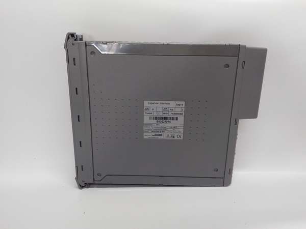
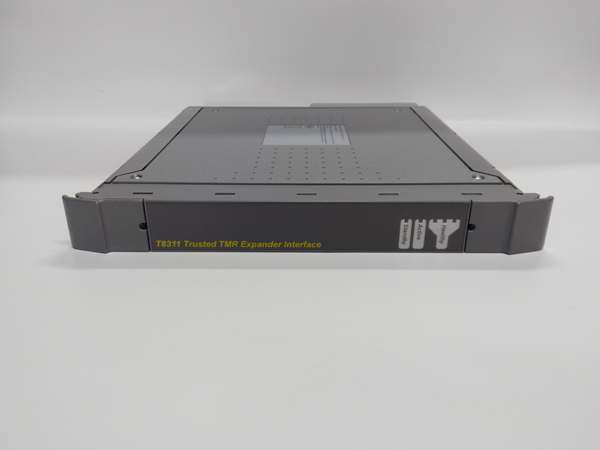
- Model Number: T8311
- Manufacturer: ICS Triplex (Emerson)
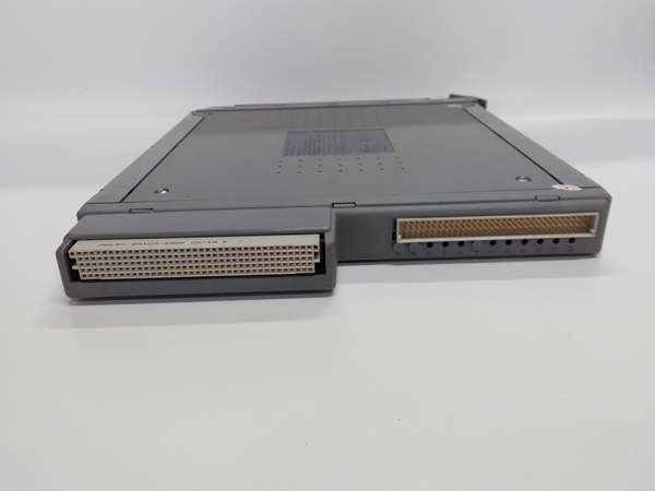
- Communication Links: 2 × redundant expander links (proprietary Trusted protocol)
- Data Transfer Rate: 250 Mbps per link (full duplex)
- Maximum Remote Rack Distance: 1000 m (3280 ft) over fiber optic cable; 100 m (328 ft) over copper
- Isolation Rating: 2500 V DC link-to-backplane; 1500 V DC link-to-link
- Supported Remote Racks: Up to 8 Trusted expander racks per module
- Operating Temperature: -40°C to 70°C (-40°F to 158°F)
- Power Supply: 20–32 V DC (redundant backplane-powered), 10 W typical power consumption
- Diagnostics: Link status monitoring, remote rack health checks, communication error logging, module self-test
- Certifications: IEC 61508 SIL 3, ATEX, IECEx, FM Class I Div 2, CSA
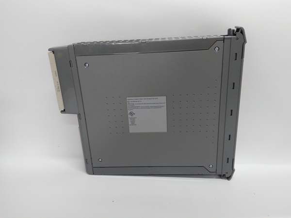
- Physical Form Factor: Single-slot rack-mounted, 266 mm (H) × 31 mm (W) × 303 mm (D), 1.0 kg (2.2 lbs)
- Hot-Swap Capability: Supported (no system shutdown required in redundant configurations)
ICS TRIPLEX T8311
Field Application & Problem Solved
In large-scale industrial facilities—refineries, chemical plants, and power generation complexes—the biggest challenge is connecting remote I/O racks to the main SIS controller without introducing communication latency or single points of failure. Legacy non-redundant interface modules create bottlenecks: slow data transfer rates delay safety signals, and a single link failure disables an entire remote I/O rack, blinding the SIS to critical process variables (e.g., tank levels, pump status) in that area. Worse, non-safety-rated modules can’t meet SIL 3 compliance, exposing plants to regulatory penalties and safety risks.
The T8311 solves these problems. You’ll find it deployed in refineries where remote I/O racks monitor storage tank farms—its dual redundant links ensure that even if one fiber optic cable is cut (a common issue in busy plant yards), communication with the main controller remains uninterrupted. In chemical plants with distributed process units, it connects remote I/O racks that control reactor feed valves, delivering 250 Mbps data transfer speeds that eliminate latency for safety-critical signals. Offshore platforms use it to link I/O racks on different deck levels, leveraging its wide temperature range and corrosion-resistant design to withstand salt spray and extreme weather.
Its core value is twofold: first, redundant expander links eliminate single-point communication failures, ensuring 100% uptime for remote I/O rack connectivity. Second, high-speed data transfer (250 Mbps) ensures that safety signals from remote racks reach the main controller in <1 ms, critical for real-time ESD system response. Unlike generic remote I/O interfaces, the T8311 is fully integrated with the Trusted system’s diagnostic framework—operators can monitor link health, remote rack status, and communication errors from the HMI, allowing them to schedule maintenance before a failure occurs.
Installation & Maintenance Pitfalls (Expert Tips)
Redundant Links Must Use Separate Physical Paths
Rookies often run both redundant expander links in the same cable tray or conduit, defeating the purpose of redundancy. If a single cable tray is damaged (e.g., by a construction vehicle), both links fail, and the remote I/O rack goes offline. Always route each link via a separate, physically isolated path—for fiber optic links, use separate cable trays on opposite sides of the plant. For copper links, maintain a minimum separation of 30 cm (12 inches) from power cables to reduce EMI interference. Label links clearly (Link 1 = Primary, Link 2 = Backup) in the wiring diagram and verify path separation during commissioning.
Fiber Optic Termination Requires Clean, Precise Cuts
A common mistake with fiber optic links is poor termination—scratched or dirty connectors cause signal loss, intermittent communication drops, and high error rates. These issues are hard to trace because they don’t trigger immediate faults—they just degrade performance over time. Always use a precision fiber cleaver to cut cables, and clean connectors with lint-free wipes and isopropyl alcohol before termination. Use only OEM-specified fiber optic connectors (LC duplex is standard for the T8311) and test link signal strength with an optical power meter after installation. A signal loss of >3 dB indicates a bad termination that needs rework.
Hot-Swap Requires Remote Rack Status Verification First
Yes, the T8311 supports hot-swapping, but pulling the module without checking the remote rack status is a rookie mistake that can disable an entire remote I/O bank. Before replacement, log into the Trusted HMI and confirm that both expander links are active and the remote rack is communicating via the primary link. If the module is running on a single link (backup link failed), a hot-swap will trigger a communication loss fault that could force the remote rack into a safe state. Always ensure both links are healthy before swapping, and disable the module’s communication group in the controller software to prevent failover loops during replacement.
Grounding Copper Links Prevents EMI-Induced Errors
For copper-based expander links, improper grounding is the leading cause of communication errors. Rookies often ground both ends of the copper cable, creating ground loops that introduce noise into the signal. Use shielded twisted-pair (STP) copper cable for all links, and terminate the shield only at the main controller rack end—leave the remote rack end floating. This eliminates ground loops and reduces EMI pickup from nearby VFDs or high-voltage cables. For copper links run in high-noise areas (e.g., near motor control centers), use metal conduit to further reduce interference.
ICS TRIPLEX T8311
Technical Deep Dive & Overview
The T8311 is a redundant expander interface module engineered for Trusted Series SIS, designed to provide high-speed, fault-tolerant communication between main controller racks and remote I/O expander racks. At its core, it uses a dedicated communication processor that manages dual redundant expander links, offloading this work from the main Trusted CPU to keep safety logic scan times low. The module operates in an active-standby redundancy mode: the primary link handles normal communication, and the backup link takes over instantly (<1 ms failover time) if the primary link experiences signal loss, high error rates, or physical damage.
What sets the T8311 apart from generic remote I/O interfaces is its safety-focused design. Unlike standard modules that prioritize throughput over reliability, the T8311 uses a proprietary Trusted protocol that prioritizes safety-critical signals—ESD triggers, valve status, and alarm signals are transmitted before non-essential data (e.g., diagnostic logs). This ensures that safety signals reach the main controller with zero latency, even during peak communication loads. The module also performs continuous health checks on remote I/O racks—monitoring power supply status, module health, and backplane communication—and triggers an HMI alarm if any fault is detected in the remote rack.
The T8311 communicates with the main Trusted controller via the redundant backplane, and with remote I/O racks via fiber optic or copper links. For fiber optic links, it supports distances up to 1000 m, making it ideal for large plants where remote I/O racks are located far from the main control room. Its built-in diagnostics log communication errors, link status changes, and remote rack faults with a 1 ms time stamp, enabling operators to perform root-cause analysis quickly if a communication issue occurs.
In summary, the T8311 is not a generic remote I/O interface—it’s a safety-critical component that ensures seamless connectivity between main and remote SIS components. Its redundant links, high-speed data transfer, and integrated diagnostics make it indispensable for large-scale industrial facilities where remote I/O rack uptime is non-negotiable.


