
Description
Hard-Numbers: Technical Specifications
- Channel Count: 16 isolated digital output channels
- Output Type: Relay output (SPDT) with galvanic isolation
- Output Voltage Rating: 24VDC nominal (up to 30VDC continuous)
- Output Current Rating: 2A per channel at 24VDC resistive load
- Channel Isolation: 2500VAC channel-to-channel isolation
- Module Isolation: 5000VAC module-to-backplane isolation
- Contact Material: Silver alloy (AgCdO or equivalent)
- Contact Rating: 5A at 120VAC, 5A at 28VDC resistive; lower for inductive loads
- Response Time: <10 ms relay operation time
- Diagnostic Coverage: 99.9% per IEC 61508 (SIL 3)
- Operating Temperature: -40°C to +70°C full load; -40°C to +85°C storage
- Humidity: 10–90% RH non-condensing
- Power Consumption: ~15W typical (varies by channel activation and load)
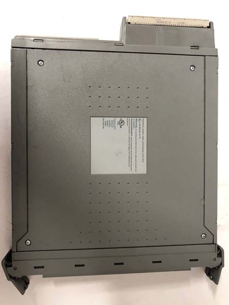
- Certifications: TÜV SIL 3, ATEX, IECEx, FM, UL
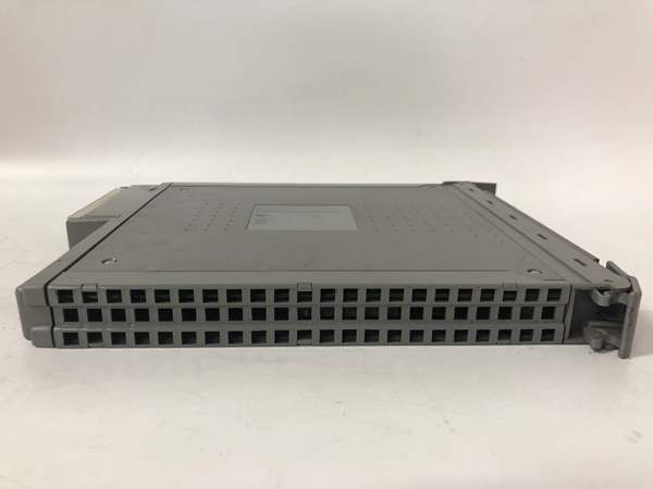
- Dimensions: 208 mm × 120 mm × 55 mm (8.2″ × 4.7″ × 2.2″)
- Mounting: Hot-swappable in Tricon/Tricon CX chassis slots
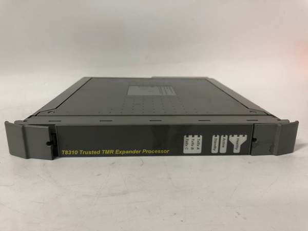
ICS Triplex T8310
The Real-World Problem It Solves
Safety output modules need to reliably energize and de-energize final elements—solenoid valves, motor starters, alarm horns—while ensuring that a single internal fault doesn’t cause the output to get stuck in the wrong state. A standard digital output module can’t detect relay contact welding or stuck conditions, leading to failure to trip on demand or failure to reset after a safety condition clears. The T8310 provides isolated relay outputs with comprehensive diagnostics that monitor output state, detect contact faults, and verify circuit continuity. When the Tricon commands a safety shutdown, this module executes the command and confirms the final element actually responded.
Where you’ll typically find it:
- Tricon/Tricon CX systems controlling ESD valves, vent valves, and shutdown solenoids
- Process safety applications requiring SIL 3 certified output modules with feedback
- Critical shutdown systems where output verification is mandatory for safety integrity
Bottom line: The T8310 is the hands of your safety system—when the Tricon says “shut it down,” this module actually does it and tells you it happened.
Hardware Architecture & Under-the-Hood Logic
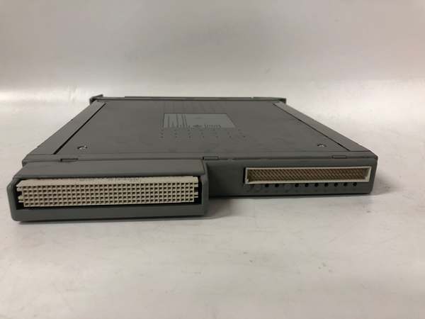
The T8310 is a 16-channel isolated digital output module designed for the Tricon and Tricon CX safety platforms. It slides into the Tricon chassis and communicates with the Tricon controller via the backplane. Inside, it features a redundant dual-processor architecture with 16 SPDT relay outputs, each with dedicated diagnostic monitoring. Each relay has galvanic isolation, feedback sensing, and fault detection circuitry for SIL 3 compliance.
-
Channel Output Circuitry: Each of the 16 channels has an SPDT (Form C) relay providing normally-open (NO) and normally-closed (NC) contacts. The relay is controlled by a solid-state driver from the dual-processor logic. Output voltage is 24VDC nominal (up to 30VDC), and current rating is 2A per channel at 24VDC resistive. For inductive loads (solenoids, motor starters), the module includes flyback diode protection or recommends external suppression.
-
Output State Verification: Each channel includes a feedback sensor that monitors the actual output state. The feedback sensor detects whether the relay contacts are in the commanded position (open/closed). If the Tricon commands “energize” but the feedback sensor reports “de-energized,” a contact fault (welded or stuck) is immediately flagged. Conversely, if the Tricon commands “de-energize” but feedback reports “energized,” the relay has failed to open and is flagged as a fault. This verification loop ensures output integrity.
-
Dual Redundant Processing: The module contains two independent microcontroller-based processing chains that simultaneously drive and verify each output channel for SIL 3 compliance. Both chains compare their results and validate feedback signals. If Chain A commands “ON” and Chain B’s feedback disagrees, a diagnostic fault is immediately flagged. The Tricon controller automatically takes predefined action—bypassing the faulty channel, triggering a safety shutdown, or activating redundant outputs based on configuration.
-
Comprehensive Diagnostics: The module runs continuous, channel-level diagnostics, including:
- Relay contact welding detection (stuck-closed fault)
- Relay contact stuck-open detection (stuck-open fault)
- Open circuit detection on output wiring (wire break)
- Short circuit detection (line-to-line or line-to-ground)
- Output overcurrent detection (exceeding 2A limit)
- Feedback sensor integrity checks
- Relay coil integrity monitoring
- Channel isolation monitoring
- Module-to-backplane isolation testing (periodic self-test)
-
Hot-Swap Capability: In redundant Tricon systems, a T8310 module can be physically removed and replaced while the system is running. The remaining module (in a dual-redundant I/O configuration) maintains safety function during the swap. When the new module is inserted, it automatically syncs configuration and data with the Tricon controller. The Tricon performs a diagnostic check before bringing the new module online, ensuring it meets SIL 3 integrity standards before operation.
ICS Triplex T8310
Field Service Pitfalls: What Rookies Get Wrong
Overloading Channels Beyond 2A Rating
I’ve seen techs wire multiple solenoids in parallel to a single T8310 channel output because “they’re small, it should be fine.” The problem: each solenoid has inrush current that can exceed 2A during energization. Combined inrush causes the channel to trip on overcurrent or the relay contacts to weld due to excessive arcing. Welded contacts can’t open when needed, and the safety function fails.
- Field Rule: Calculate total load current for each channel, including inrush for inductive loads. Ensure steady-state current is <2A and inrush current is <5A (for short durations <100 ms). If multiple devices must be controlled, use separate channels or install an intermediate relay with appropriate current rating. Measure actual inrush current with a clamp meter during commissioning—don’t rely on nameplate data alone.
Using the Module Output Directly for Motor Starters
Rookies connect T8310 outputs directly to motor starter coils (large contactors, 24VDC coils). These coils have high inductance and generate significant flyback voltage when de-energized. The T8310’s internal suppression isn’t designed for such loads—flyback can damage the relay driver or cause arcing at the contacts, leading to premature failure or contact welding. Additionally, the T8310’s 2A rating is often insufficient for large motor starter coils.
- Quick Fix: Use the T8310 output to drive an intermediate power relay (e.g., ice cube relay) with appropriate coil rating and flyback suppression. The intermediate relay handles the motor starter coil. This protects the T8310 from inductive flyback and overcurrent. Verify the intermediate relay’s contact rating matches the motor starter coil requirements.
Wiring Output Feedback to the Same Channel
I’ve seen installations where output feedback is wired back to the same T8310 channel’s feedback input (not a standard configuration, but techs attempt it for “self-verification”). This creates a circular reference—if the output is welded, feedback still shows “good” because it’s reading the same welded contact. The T8310 can’t detect the fault because it’s comparing the output to itself rather than to an independent field feedback (e.g., discrete input from valve position switch).
- Field Rule: Never use T8310 output feedback as proof of valve or solenoid position. The feedback only confirms that the relay operated, not that the final element moved. For safety-critical outputs, always use a separate feedback input (e.g., valve position switch, flow switch) on a T8311 digital input module. The Tricon logic should verify both “output commanded ON” AND “feedback indicates valve moved” before considering the safety action complete.
Ignoring Overcurrent Diagnostics on Degraded Channels
New engineers assume “no fault alarm” means all outputs are healthy. They don’t check T8310 channel diagnostic data. Over time, a channel’s current draw may increase due to degraded wiring or a failing load, approaching the 2A limit. The module flags a “degraded” warning (not a full fault) because current is high but below the threshold. If ignored, the channel eventually trips on overcurrent at the worst possible moment.
- Field Rule: During routine maintenance, inspect T8310 channel diagnostic data (output current, feedback verification) using the Tricon Maintenance Tool (TMT). Document current draw for each active channel and monitor trends over time. If any channel shows increasing current trend or degraded warnings, investigate the field wiring and load before the channel trips. Proactive replacement beats emergency downtime.
Improper Suppression on Inductive Loads
The T8310 includes some flyback protection, but for large inductive loads (solenoids, motor starters), external suppression is mandatory. Rookies omit suppression diodes or MOVs, causing high-voltage transients to arc across relay contacts when de-energizing. This contact erosion leads to increased contact resistance, higher power dissipation, and eventual contact welding.
- Quick Fix: Install a suppression diode (flyback diode) across the coil of each inductive load, with cathode to positive, anode to negative. For AC loads, use an RC snubber or MOV across the coil. Verify suppression components are rated for the coil voltage and inductive energy. After installation, test de-energization with an oscilloscope—flyback voltage should be clamped to <30V for 24VDC coils. Don’t rely on the T8310’s internal protection alone.
Commercial Availability & Pricing Note
Please note: The listed price is for reference only and is not binding. Final pricing and terms are subject to negotiation based on current market conditions and availability.


