
Description
Hard-Numbers: Technical Specifications
- Channel Count: 8 isolated digital input channels
- Input Type: 24VDC wetting voltage (sourcing/sinking configurable)
- Input Voltage: 20.4–27.6VDC nominal; 18–30VDC operating range
- Input Current per Channel: 4–10 mA typical for 24VDC wetting
- Input Resistance: ~2.4 kΩ per channel
- Channel Isolation: 2500VAC channel-to-channel isolation
- Module Isolation: 5000VAC module-to-backplane isolation
- Response Time: <1 ms typical for high-speed safety channels
- Scan Rate: <10 ms module update rate
- Diagnostic Coverage: 99.9% per IEC 61508 (SIL 3)
- Operating Temperature: -40°C to +70°C full load; -40°C to +85°C storage
- Humidity: 10–90% RH non-condensing
- Power Consumption: ~10W typical (varies by channel count)
- Certifications: TÜV SIL 3, ATEX, IECEx, FM, UL
- Dimensions: 208 mm × 120 mm × 55 mm (8.2″ × 4.7″ × 2.2″)
- Mounting: Hot-swappable in Tricon/Tricon CX chassis slots
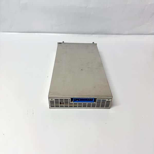
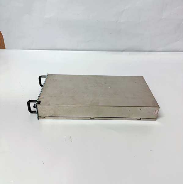
ICS TRIPLEX T8231
The Real-World Problem It Solves
Safety systems can’t afford false signals or missed trips. A standard digital input module can’t distinguish between valid field signals and induced noise, leading to spurious safety shutdowns or failure to act on critical alarms. The T8231 provides fully isolated digital input channels with comprehensive diagnostics that detect wire breaks, shorts, and signal degradation. Each channel has its own isolation barrier, preventing fault propagation between channels. When an emergency 终止 button is pressed or a pressure switch trips, this module reads it correctly and reports it to the Tricon controller without hesitation.
Where you’ll typically find it:
- Tricon/Tricon CX systems reading emergency 终止s, pressure switches, and valve position feedback
- Process safety applications requiring SIL 3 certified input modules
- Critical shutdown systems where single-channel failures can’t compromise overall system availability
Bottom line: The T8231 is the first line of defense for your safety system—when a fault happens, this module makes sure the Tricon knows about it before the situation escalates.
Hardware Architecture & Under-the-Hood Logic
The T8231 is an isolated 8-channel digital input module designed for the Tricon and Tricon CX safety platforms. It slides into the Tricon chassis and communicates with the Tricon controller via the backplane. Inside, it features a redundant dual-processor architecture and fully isolated channel input circuitry. Each of the 8 channels has its own isolation barrier, diagnostic monitoring, and signal conditioning stages, ensuring that faults on one channel don’t affect others.
-
Channel Input Circuitry: Each channel starts with an opto-isolation barrier that provides 2500VAC channel-to-channel isolation, preventing ground loops and fault propagation between channels. The input is configurable as sourcing or sinking via DIP switches (user selects input polarity). For each channel, the module applies a wetting voltage (24VDC) to dry contact inputs or monitors current for active inputs.
-
Dual Redundant Processing: The module contains two independent microcontroller-based processing chains that simultaneously read and validate each input channel for SIL 3 compliance. Both chains continuously compare their results to ensure consistency. If Chain A reads “ON” and Chain B reads “OFF” for a channel, a diagnostic fault is immediately flagged. The Tricon controller automatically takes predefined action—bypassing the faulty channel while keeping healthy ones online or triggering safety interlocks based on severity.
-
Diagnostic Monitoring Engine: The module runs continuous, channel-level diagnostics on every input, including:
- Wire break detection via voltage or current sensing
- Short circuit detection (line-to-line or line-to-ground)
- Stuck-at-0 or stuck-at-1 fault detection
- Input signal integrity checks (out-of-range voltage/current)
- Channel-to-ground isolation monitoring
- Module-to-backplane isolation testing (periodic self-test)Diagnostic data is reported to the Tricon controller via the backplane, allowing operators to monitor health in real-time.
-
Redundant Backplane Communication: The module communicates with the Tricon controller via two independent backplane interfaces (Left and Right). If one backplane path fails (e.g., chassis slot fault), the other maintains communication. The Tricon controller automatically switches between interfaces without losing data or interrupting safety function. This redundancy ensures the T8231 remains responsive even if part of the backplane fails.
-
Hot-Swap Capability: In redundant Tricon systems, a T8231 module can be physically removed and replaced while the system is running. The remaining module (in a dual-redundant I/O configuration) maintains safety function during the swap. When the new module is inserted, it automatically syncs configuration and data with the Tricon controller. The Tricon performs a diagnostic check before bringing the new module online, ensuring it meets SIL 3 integrity standards before operation.
Field Service Pitfalls: What Rookies Get Wrong
Mixing Sourcing and Sinking Inputs on the Same Module
New engineers see “configurable polarity” and start wiring sourcing inputs (PNP sensors) and sinking inputs (NPN sensors) on the same module. The issue: the T8231 has a single global DIP switch setting that configures all 8 channels to either sourcing or sinking. Mixing polarities results in some channels not working or false signal readings. If you need both polarities, you must split them onto separate modules.
- Field Rule: Configure the entire module for one input polarity (sourcing or sinking) via the DIP switches. If your application requires both polarities, use two separate T8231 modules—one for sourcing, one for sinking. Verify input polarity settings during commissioning and document them in loop sheets to avoid confusion during future service.
Forgetting to Install Backplane Termination Resistors
I’ve seen techs omit the termination resistors (supplied with the module) when installing the T8231 in a Tricon chassis slot. The termination resistors match backplane impedance, preventing signal reflections that cause communication errors or intermittent faults. Without termination, the module may experience “no communication” errors with the Tricon controller, leading to false alarms or module unavailability.
- Quick Fix: Install termination resistors on the left and right backplane connectors when the module is placed in the end slot of a Tricon chassis. When installing between other modules, omit termination unless specified in Tricon installation documentation. Verify module presence and communication via the Tricon diagnostic menu after installation—if the module is not recognized, check termination resistors first.
Overlooking Cable Length Limits for 24VDC Inputs
Standard 24VDC wetting voltage has limited range for long field cable runs (>100m). Rookies use 18AWG wire for cable lengths of 150m or more. Voltage drop across the wire reduces available wetting voltage to below 18VDC, which is outside the T8231 operating range. The module may not reliably detect contact closure, leading to intermittent signal faults or missed trips.
- Field Rule: Calculate voltage drop for field cable runs using the formula V_drop = (2 × L × I) / R_wire. Use the minimum wire gauge required to keep voltage drop <2V for 24VDC inputs. For runs >100m, use 16AWG or 14AWG wire to ensure sufficient wetting current reaches the field device. Measure actual voltage at the field end during commissioning to confirm it falls within 18–30VDC range.
Tying Multiple Input Channels Together on One Termination
I’ve seen installations where multiple limit switch contacts are wired in parallel to a single T8231 channel input. The result: if one contact fails open, it doesn’t trigger a fault because the other contacts are still closed. The T8231’s diagnostics can’t detect a single open contact in a parallel configuration—defeating its diagnostic purpose. Each limit switch should use its own isolated channel.
- Field Rule: Each critical safety input must have its own dedicated isolated channel on the T8231. Never parallel multiple field devices onto one channel unless they are part of a redundant safety function and specifically wired for that purpose (e.g., redundant valve feedback). If parallel wiring is unavoidable, verify that Tricon software is configured to detect faults in that scenario.
Ignoring Module Health Diagnostics Until a Fault Occurs
New engineers assume “no fault alarm” means everything is working correctly. They don’t check the T8231 module diagnostic data—even though the Tricon constantly reports channel health, isolation resistance, and signal levels. Over time, a channel’s isolation resistance may decrease (due to dirt, moisture, or cable damage) until it falls below the safe threshold. By the time the module triggers a fault, the isolation barrier may be compromised, potentially exposing technicians to dangerous voltages.
- Field Rule: During routine maintenance, inspect T8231 module diagnostic data (isolation resistance, signal levels) using the Tricon Maintenance Tool (TMT). Document isolation resistance values and monitor trends over time—if isolation resistance drops below 2.5MΩ, plan for module replacement or field wiring inspection. Proactively address minor degradation before it becomes a critical safety issue.
Commercial Availability & Pricing Note
Please note: The listed price is for reference only and is not binding. Final pricing and terms are subject to negotiation based on current market conditions and availability.


