
Description
Key Technical Specifications
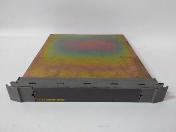
- Model Number: T8191
- Manufacturer: ICS Triplex (Emerson)
- Channel Count: 2 independent safety relay output channels (forced-guided contacts)
- Output Rating: 24 VDC (5A resistive load) / 230 VAC (3A resistive load) per channel
- Isolation Rating: 3000V AC channel-to-backplane; 1500V AC channel-to-channel (1-minute withstand test)
- Redundancy Architecture: Triple Modular Redundancy (TMR) with majority voting logic
- Contact Type: DPDT (Double-Pole Double-Throw) forced-guided (positive-guided) contacts
- Operating Temperature: -40°C to 70°C (-40°F to 158°F)
- Power Supply: 20–32 VDC (redundant backplane-powered), 8W typical power consumption
- Diagnostics: Continuous contact weld detection, coil integrity monitoring, module self-test
- Certifications: IEC 61508 SIL 3, ATEX, IECEx, FM Class I Div 2, CSA
- Physical Form Factor: Single-slot rack-mounted, 266mm (H) × 31mm (W) × 303mm (D), 1.1kg (2.42lbs)
- Hot-Swap Capability: Supported (no system shutdown required in redundant configurations)

ICS Triplex T8191
Field Application & Problem Solved
In high-risk industrial environments—refineries, chemical plants, and nuclear power auxiliary systems—the most critical failure point in an ESD system is the final output stage that triggers shutdowns. Legacy non-forced-guided relay modules can fail silently (e.g., contact welds) and fail to de-energize a valve or pump, allowing a hazard to escalate into a catastrophic event. Non-TMR modules add another layer of risk: a single component failure can disable the output channel entirely, leaving the SIS unable to execute a shutdown command.
The T8191 solves both problems. You’ll find it in the final stage of ESD systems, where it switches the power to critical solenoid valves that isolate fuel lines, or to shutdown relays that trip turbine generators during overspeed events. In chemical batch processing, it controls the emergency isolation valves that contain hazardous material leaks—its forced-guided contacts ensure that if a contact welds, the module immediately flags a fault and defaults to a safe state (valve closed). Offshore, its wide temperature range and corrosion-resistant design hold up to salt spray and humidity, eliminating the need for costly environmental enclosures.
Its core value is twofold: first, forced-guided contacts eliminate the risk of silent contact weld failures—a common cause of SIS failures that bypass traditional diagnostics. Second, TMR redundancy ensures a single module component failure won’t disable an output channel. Unlike standard relay modules, the T8191 doesn’t require external safety relays to meet SIL 3 compliance, cutting down on wiring complexity and failure points in the control loop. For plant operators, this means meeting regulatory safety requirements while reducing unplanned downtime from false ESD trips or failed shutdown commands.
Installation & Maintenance Pitfalls (Expert Tips)
Forced-Guided Contacts Require Correct Load Wiring
Rookies often wire only one pole of the DPDT contacts, defeating the purpose of forced-guided design. These contacts are engineered to move in tandem—if one pole welds, the other pole will not close, and the module will detect the mismatch and trigger a fault. Always wire both poles of each channel to the load (e.g., solenoid valve coil) and the safety circuit. This redundancy is critical for contact weld detection—skipping it will leave you blind to a dangerous failure mode that could prevent an ESD shutdown.
Contact Rating Must Match Load Type (Resistive vs. Inductive)
A common mistake is overloading the T8191’s contacts with inductive loads (e.g., motor starters, solenoid valves) without derating the current. The module’s 5A DC/3A AC rating is for resistive loads—inductive loads (which have high inrush currents) require a 50% derating. For example, a solenoid valve with a 2A steady-state current and 10A inrush current will damage the contacts over time. Always check the load’s inrush current specification, derate the contact rating accordingly, and use surge suppressors (varistors or diodes) across inductive loads to reduce inrush stress.
Hot-Swap Requires Output Group Deactivation First
Yes, the T8191 supports hot-swapping, but pulling the module without deactivating its output group is a rookie mistake that will trigger an unplanned ESD trip. Before replacement, log into the Trusted HMI and put the output group in “test mode”—this tells the controller to disable the channel outputs and ignore fault signals during the swap. Wait 10 seconds for the controller to acknowledge, then remove the module. After reinstallation, take the group out of test mode only after the module syncs with the redundant pair (verify via the front-panel “SYNC” LED). Rushing this step will cost you hours of downtime.
Coil Integrity Monitoring Depends on Proper Power Wiring
The T8191’s built-in coil integrity monitoring checks for broken relay coils, but it only works if the module’s backplane power is wired correctly. Rookies often use a non-redundant power supply for the module, which means a power loss will disable the monitoring function. Always wire the module to the Trusted system’s redundant 20–32 VDC backplane power supply. This ensures coil monitoring remains active even if one power supply fails, and it prevents false “coil fault” alarms caused by voltage fluctuations.

ICS Triplex T8191
Technical Deep Dive & Overview
The T8191 is a 2-channel TMR safety relay output module engineered for Trusted Series SIS, designed to provide fail-safe switching of critical final elements in high-risk industrial applications. At its core, it uses three independent relay driver circuits (one per TMR leg) that receive output commands from the Trusted controller, vote on the correct state, and energize the relay coils. The majority voting logic ensures a single driver circuit failure (e.g., a faulty transistor) is ignored—only if two legs fail does the module trigger a system alarm.
What sets the T8191 apart from standard relay modules is its forced-guided (positive-guided) DPDT contacts. These contacts are mechanically linked so they cannot move independently—if one contact welds closed due to arcing or overload, the other contact will not close, creating a detectable state mismatch. The module’s diagnostics continuously monitor contact position relative to the commanded state, logging a fault within 10ms of a mismatch and defaulting the channel to a safe state (de-energized). This eliminates silent contact weld failures, a top cause of SIS non-compliance during regulatory audits.
The module communicates with the Trusted CPU via the redundant backplane using the proprietary Triplex protocol, with a latency of less than 2ms per command—critical for real-time ESD system response. Its 3000V AC isolation rating protects the control system from high-voltage transients in the field wiring, and its dual-rated contacts (24VDC/230VAC) eliminate the need for separate modules for DC and AC loads. Unlike external safety relays, the T8191 integrates seamlessly with the Trusted system’s diagnostics, allowing operators to monitor contact health and coil integrity from the HMI without manual testing.
In summary, the T8191 is a safety-critical output module built for the harsh realities of industrial control—not lab conditions. Its forced-guided contacts, TMR redundancy, and integrated diagnostics make it indispensable for ESD systems where a single failure could lead to disaster. For field service engineers, it’s a reliable workhorse that eliminates the guesswork from safety output switching, ensuring compliance and uptime in equal measure.


