
Description
Hard-Numbers: Technical Specifications
- Compatible Flame Detectors: Honeywell C7012A, C7027A, C7035A, C7044A series UV detectors
- Input Signal: UV detector current signal (microamp range)
- Power Supply: 24VAC or 24VDC (20–30V range typical)
- Relay Outputs:
- Flame present (SPDT, Form C): 5A at 120VAC, 5A at 24VDC resistive
- Alarm/fault (SPDT, Form C): 5A at 120VAC, 5A at 24VDC resistive
- Response Time: <2 seconds for flame detection
- Flame Signal Adjustment: Adjustable sensitivity potentiometer
- Self-Test: Automatic self-test circuitry with periodic detector diagnostics
- Isolation: 1500VAC input-output isolation
- Operating Temperature: -40°F to +140°F (-40°C to +60°C)
- Storage Temperature: -67°F to +185°F (-55°C to +85°C)
- Enclosure: NEMA 4X (weatherproof) enclosure option available
- Approvals: UL, FM, CSA, CE, ATEX, IECEx
- Dimensions: 4.5″ × 4.5″ × 3″ (114 mm × 114 mm × 76 mm)
- Mounting: Wall mount or panel mount with 4-hole pattern
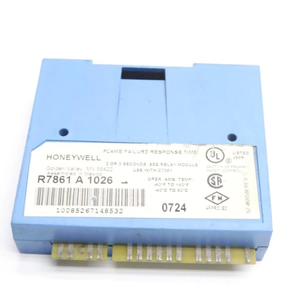
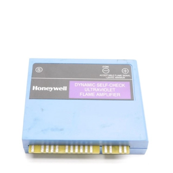
Honeywell R7861A1026
The Real-World Problem It Solves
Burners need reliable flame detection to prevent fuel from being fed into an unlit firebox—a condition that causes explosions. A simple photo-eye or thermal switch can’t distinguish between actual flame and hot refractory or glowing debris. The R7861A1026 works with UV flame detectors (C7012A, C7027A) that sense ultraviolet radiation emitted only by combustion. The amplifier conditions the weak microamp signal from the detector, performs automatic self-tests, and provides relay outputs for flame status. When the flame goes out, the R7861A1026 triggers a safety shutdown within 2 seconds—closing fuel valves and preventing hazardous conditions.
Where you’ll typically find it:
- Boiler control cabinets amplifying UV flame detector signals for burner management systems
- Process heater firebox monitoring requiring rapid flame failure detection
- Incinerators and thermal oxidizers with combustion safety interlocks
Bottom line: It’s the eyes of your burner safety system—when the flame dies, this amplifier sees it first and cuts the fuel before the firebox fills with gas.
Hardware Architecture & Under-the-Hood Logic
The R7861A1026 is an analog amplifier module designed to interface with Honeywell UV flame detectors in the C7000 series. It mounts in a control cabinet and provides power to the UV detector, receives the weak current signal proportional to UV radiation intensity, conditions that signal, and drives relay outputs based on flame presence. The module includes automatic self-test circuitry that periodically checks detector integrity and internal amplification paths.
-
Detector Power Supply: The amplifier provides 24VAC or 24VDC to the UV detector via the signal loop. The UV detector contains a photomultiplier tube or solid-state UV sensor that generates a small current (typically 1–100 microamps) proportional to the UV radiation intensity detected from the flame. The current flows back to the amplifier on the same pair of wires (2-wire loop-powered configuration).
-
Signal Conditioning: The weak microamp current from the detector is converted to a voltage signal via an input resistor or transimpedance amplifier. This voltage signal is filtered to remove noise and then amplified to a level suitable for comparison against adjustable thresholds. A sensitivity potentiometer on the front panel allows field adjustment of the detection threshold—turning clockwise increases sensitivity (detects weaker flames), counter-clockwise decreases sensitivity (reduces false alarms from hot refractory).
-
Flame Decision Logic: The conditioned signal is compared against two thresholds:
- Flame Present Threshold: If signal > threshold, flame is detected. The “Flame Present” relay energizes (NO contact closes).
- Flame Failure Threshold: If signal drops below threshold for >2 seconds, flame failure is declared. The “Flame Present” relay de-energizes (NO contact opens, NC contact closes to trigger safety shutdown).A small deadband between thresholds prevents relay chatter when signal fluctuates near the threshold.
-
Automatic Self-Test: The amplifier performs periodic self-tests (typically every 1–2 minutes) to verify detector and amplifier integrity. During self-test, the amplifier briefly modulates the detector supply voltage or injects a test signal, checking that the detector responds correctly. If the detector fails the test (no response, stuck at high output, or open circuit), the amplifier triggers the “Alarm/Fault” relay and may disable the flame detection output. The self-test interval and logic are fixed internally per Honeywell design.
-
Relay Outputs: Two independent SPDT (Form C) relays provide isolated outputs:
- Flame Present Relay: Energized when flame is detected (NO contact closed). De-energizes on flame failure (NC contact closes to trigger safety shutdown).
- Alarm/Fault Relay: Energized in normal operation. De-energizes on detector fault, self-test failure, or internal amplifier fault. Typically wired to an alarm circuit or DCS input for operator notification.
-
Diagnostic Indicators: Front-panel LEDs indicate system status:
- Flame On: Green LED lights when flame is detected
- Alarm/Fault: Red LED lights on fault condition
- Self-Test: Yellow LED (if equipped) flashes during self-test cycle

Honeywell R7861A1026
Field Service Pitfalls: What Rookies Get Wrong
Setting Sensitivity Too High on Startup
I’ve seen techs crank the sensitivity potentiometer all the way clockwise “to make sure we don’t miss the flame.” The problem: hot refractory, glowing burner parts, or even ambient light (for some detectors) generates enough UV signal to trigger a false flame indication. The amplifier shows “flame present” when the burner is actually off—fuel valve stays open, unburned fuel accumulates, and when ignition finally happens, you get a boom.
- Field Rule: Perform sensitivity adjustment during actual burner operation with the firebox at normal operating temperature. Start with sensitivity at mid-range, then slowly increase until flame is reliably detected with the burner at minimum fire rate. Verify that the “Flame On” LED and relay both extinguish when the burner is shut off. If flame indication persists with no flame, reduce sensitivity.
Wiring Detector Without Shielding
New engineers run UV detector cables in the same cable tray as ignition high-voltage leads or burner motor power cables. EMI from these sources induces noise on the microamp detector signal, causing erratic relay operation—false flame failure trips or phantom flame indication. The amplifier chatters and may trigger spurious safety shutdowns.
- Quick Fix: Use twisted-pair shielded cable for UV detector wiring. Terminate the shield at the amplifier end only (single-point grounding) unless the detector housing is already grounded—then terminate at the detector end. Keep detector cables at least 12 inches away from ignition cables, motor leads, and VFD outputs. If crossing is unavoidable, cross at 90° angles.
Ignoring the Self-Test Fault LED
Techs install the R7861A1026, verify flame detection works, and ignore the Alarm/Fault LED because the system appears operational. The self-test circuitry detects a degraded detector (weak signal response, intermittent faults) and lights the red LED, but the flame relay still works. Weeks later, the detector fails completely during a startup—the amplifier can’t see the flame, but the fault condition was already present and unaddressed.
- Field Rule: During commissioning and weekly maintenance checks, verify that the Alarm/Fault LED is off (no fault condition). If the red LED is lit, check the fault code in the amplifier manual or use a multimeter to verify detector operation. Never bypass the fault relay or ignore the indicator. Replace UV detectors at the first sign of degradation—don’t wait for complete failure.
Mounting Amplifier in High-Vibration Area
Rookies mount the R7861A1026 directly on the burner housing or near the damper actuator where vibration is severe. Over time, solder joints crack, relay contacts wear prematurely, and connections loosen due to vibration. Intermittent operation causes random flame failure trips that are a nightmare to troubleshoot—sometimes it works, sometimes it doesn’t.
- Quick Fix: Mount the amplifier in the control cabinet or a location with minimal vibration. Use vibration isolators if mounting near rotating equipment is unavoidable. Ensure mounting screws are tight and use lock washers or threadlocker. After mounting, perform a tap test—gently tap the enclosure with a screwdriver handle while monitoring the flame relay for chatter. If the relay toggles, relocate the amplifier.
Forgetting to Test with Burner at Low Fire Rate
Techs verify flame detection at high fire rate where the flame is strong and UV signal is high. They don’t test at low fire where the flame is small and weak UV output might be below detection threshold. During normal operation at low fire, the amplifier can’t see the flame, triggers flame failure, and shuts down the burner unexpectedly.
- Field Rule: Test flame detection at both high and low fire rates during commissioning. Verify that the “Flame On” LED and relay remain energized even at minimum fuel flow. If detection is unreliable at low fire, adjust sensitivity upward slightly or reposition the UV detector for better line-of-sight to the flame. Document the minimum fire rate at which detection becomes marginal.
Commercial Availability & Pricing Note
Please note: The listed price is for reference only and is not binding. Final pricing and terms are subject to negotiation based on current market conditions and availability.


