
Description
Hard-Numbers: Technical Specifications
- Function: Network processor for SafetyNet communication protocol
- Supported Protocols:
- SafetyNet redundant fieldbus (Honeywell proprietary)
- Ethernet TCP/IP (10/100/1000 Mbps)
- Modbus TCP (optional configuration)
- Port Configuration:
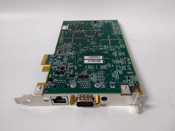
- Dual redundant Ethernet ports (RJ45)
- SafetyNet A/B network interfaces
- Processor: Embedded network processor with dedicated communication logic
- Redundancy: Supports redundant network paths and hot-swappable module replacement
- Update Rate: <100 ms typical for SafetyNet communication
- Isolation: 1500VAC isolation between network ports and internal logic
- Operating Temperature: -20°C to +60°C full load; -40°C to +70°C derated
- Storage Temperature: -40°C to +85°C
- Humidity: 10–90% RH non-condensing
- Power Consumption: 8–12W typical (varies with network load)
- Certifications: TÜV SIL 3 per IEC 61508, IEC 61511; UL/cUL Class I Div 2; CE; ATEX (varies by revision)
- Dimensions: 191 mm × 188 mm × 65 mm (7.5″ × 7.4″ × 2.6″)
- Mounting: Hot-swappable in Safety Manager controller chassis
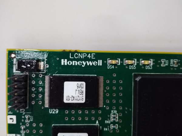
LCNP4E 51405098-100
The Real-World Problem It Solves
Safety Manager systems need reliable communication between controllers, I/O modules, and upper-level systems (DCS, HMI). A non-redundant network interface creates a single point of failure—if the network processor fails, the entire safety system loses communication with operators and may enter degraded mode. The LCNP4E provides redundant network communication paths with SIL 3 certified integrity, ensuring that a single network failure doesn’t compromise safety function availability. It handles SafetyNet protocol, Ethernet communication, and optional Modbus TCP, all in a single hot-swappable module.
Where you’ll typically find it:
- Safety Manager controller chassis providing network communication to I/O racks and operator stations
- SIL 3 ESD systems requiring redundant network paths to maintain availability
- Integrated systems where Safety Manager communicates with Experion PKS or other DCS platforms
Bottom line: It’s the nervous system of your Safety Manager—without it, your safety system is deaf, dumb, and blind to the outside world.
Hardware Architecture & Under-the-Hood Logic
The LCNP4E is a network communication processor module designed for the Honeywell Safety Manager platform. It slides into the Safety Manager controller chassis and sits on the backplane with the safety logic solver and other I/O modules. Inside, it features dual redundant Ethernet controllers, dedicated SafetyNet protocol processors, and communication logic that manages network traffic between the Safety Manager controller and external devices. The module supports hot-swapping and redundant network configurations for maximum availability.
-
Dual Redundant Ethernet Controllers: The module contains two independent Ethernet network controllers—one for Port A and one for Port B. Both ports are powered and active simultaneously, providing redundancy for network connectivity. If one port fails (cable cut, switch failure), the other maintains communication without interruption. The Safety Manager controller continuously monitors both ports for heartbeat and data integrity.
-
SafetyNet Protocol Engine: A dedicated processor handles the SafetyNet protocol—Honeywell’s proprietary safety-critical communication protocol designed for SIL 3 applications. SafetyNet includes message authentication, sequence checking, and integrity verification to ensure that messages are not corrupted, spoofed, or out of order. The protocol engine generates outgoing messages with security codes and validates incoming messages before passing data to the safety logic solver.
-
Modbus TCP Gateway (Optional): If configured, the LCNP4E can act as a gateway between SafetyNet and Modbus TCP. This allows the Safety Manager to communicate with non-Honeywell devices or DCS systems that use Modbus TCP. The gateway function handles protocol translation and mapping of Safety Manager data points to Modbus registers. Note: Modbus communication is not safety-critical—use only for monitoring, not for safety function execution.
-
Backplane Communication: The LCNP4E communicates with the Safety Manager logic solver via the controller backplane. Safety-critical data from I/O modules arrives at the logic solver, which then passes data to the LCNP4E for network transmission. Conversely, commands from HMI or DCS arrive via the LCNP4E and are passed to the logic solver for execution. All communication on the backplane is subject to SIL 3 integrity checks.
-
Redundancy and Hot-Swap: In redundant controller configurations, two LCNP4E modules can be installed—one in the primary controller chassis and one in the secondary controller chassis. Both modules communicate with the network simultaneously. If the primary LCNP4E fails, the secondary takes over network communication without operator intervention. The module supports hot-swapping in both redundant and non-redundant configurations—the controller chassis maintains operation during module replacement.
-
Diagnostic and Status Reporting: Front-panel LEDs indicate network status on both Ethernet ports (green = healthy, yellow = degraded, red = fault). The module continuously reports communication statistics (packet rates, error rates, latency) to the Safety Manager controller. Events (network loss, failover, fault) are logged in the controller event history for troubleshooting and maintenance planning.
LCNP4E 51405098-100
Field Service Pitfalls: What Rookies Get Wrong
Plugging Both Ports into the Same Switch
I’ve seen techs run both Ethernet cables (Port A and Port B) to the same network switch or even the same switch port. If that switch fails or loses power, both network paths go dead simultaneously—the Safety Manager loses all network communication, operators go blind, and alarms may not reach the control room. The redundancy is an illusion when the physical network isn’t truly independent.
- Field Rule: Verify that Port A and Port B are on physically separate network paths with independent switches. If a managed switch is used, ensure Port A and Port B are on different VLANs or at least different switch chassis. Test live failover by pulling Port A while monitoring the Safety Manager diagnostics to confirm Port B maintains communication without spurious alarms.
Using Modbus TCP for Safety-Critical Signals
Rookies see “Modbus TCP support” and start routing safety-critical signals (ESD commands, valve positions) through Modbus to the DCS for monitoring and control. Modbus has no SIL 3 certification—no message authentication, no sequence checking, no guarantee of message delivery. If network traffic corrupts a Modbus message or a man-in-the-middle attack occurs, the Safety Manager might execute the wrong command based on invalid data.
- Field Rule: Use Modbus TCP only for non-safety monitoring signals—process values, status indications, alarm annunciation. Never use Modbus for safety-critical commands (ESD initiate, valve open/close) or safety interlock data. All safety function communication must use SafetyNet protocol. Mark Modbus data points as “monitor only” in the Safety Manager project documentation.
Ignoring Link Status LEDs Until Communication Is Lost
New engineers assume “no alarm = no problem” and ignore the front-panel LED indicators on the LCNP4E. They don’t notice the yellow “degraded” LED indicating Port A has high error rates or intermittent packet loss. Port B is carrying the full network load, and when it finally fails due to overloading or a separate fault, there’s no fallback—both paths were already compromised.
- Quick Fix: During routine rounds, check the front-panel LEDs on all network processor modules. A yellow LED means one path is degraded—investigate immediately (check cables, switches, connectors). Don’t wait for a red fault LED. Preventive maintenance beats emergency downtime every time. Document LED status in shift logs to track degradation trends.
Overloading the Module with Excessive Modbus Traffic
The LCNP4E is designed primarily for SafetyNet communication. Modbus TCP is an optional gateway function with limited bandwidth. Rookies configure hundreds of Modbus points for monitoring, flooding the module with traffic. The SafetyNet processor can’t keep up, safety-critical communication gets delayed, and worst case—the safety function degrades or times out because network resources are consumed by non-safety Modbus polling.
- Field Rule: Limit Modbus TCP point count to what’s actually necessary for monitoring. Typical limit: 200–300 points maximum, depending on scan rate. If you need more monitoring data, use a dedicated gateway server or OPC server instead of overloading the Safety Manager network processor. Monitor communication statistics in the Safety Manager diagnostics—if SafetyNet error rates increase after adding Modbus points, reduce the Modbus load.
Mixing Network Cables with Power Conductors
I’ve seen network cables run right next to 480V power feeds, VFD outputs, or high-current motor leads in cable trays. EMI from these power sources induces noise on Ethernet cables, causing packet loss, CRC errors, and intermittent communication drops. The LCNP4E constantly switches between ports or generates spurious alarms due to corrupted packets.
- Quick Fix: Follow Honeywell cable routing guidelines: keep Ethernet cables at least 300mm (12″) away from power cables, cross them at 90° angles if they must intersect, and use shielded twisted-pair (STP) cables with proper shield termination. Test for EMI with a portable spectrum analyzer if the environment is particularly noisy. If noise is unavoidable, use fiber media converters for network connections.
Commercial Availability & Pricing Note
Please note: The listed price is for reference only and is not binding. Final pricing and terms are subject to negotiation based on current market conditions and availability.


