
Description
Hard-Numbers: Technical Specifications
- Control Type: Single-stage immersion temperature controller with manual reset high-limit
- Sensor Type: Bulb and capillary temperature sensor (filled system)
- Temperature Range: 100°F to 240°F (38°C to 116°C)
- Differential: 5°F to 30°F (3°C to 17°C) adjustable
- High-Limit Range: 200°F to 250°F (93°C to 121°C) with manual reset
- Switch Rating: 24VAC control circuit (SPDT switching)
- Contact Rating: 5A at 24VAC resistive; lower current for inductive loads
- Immersion Length: 4 inches (102 mm)
- Bulb Diameter: 3/8 inch (9.5 mm)
- Capillary Length: 6 feet (1.8 meters) standard
- Operating Temperature: -20°F to 250°F (-29°C to 121°C) ambient
- Storage Temperature: -40°F to 300°F (-40°C to 149°C)
- Enclosure: NEMA 1 indoor enclosure
- Approvals: UL, CSA, CE
- Dimensions: 4.5″ × 3″ × 2.5″ (114 mm × 76 mm × 64 mm)
- Mounting: Surface mount with 2-56 screw terminals
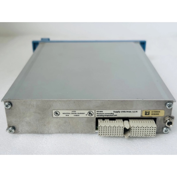
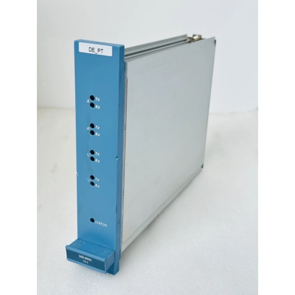
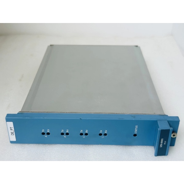
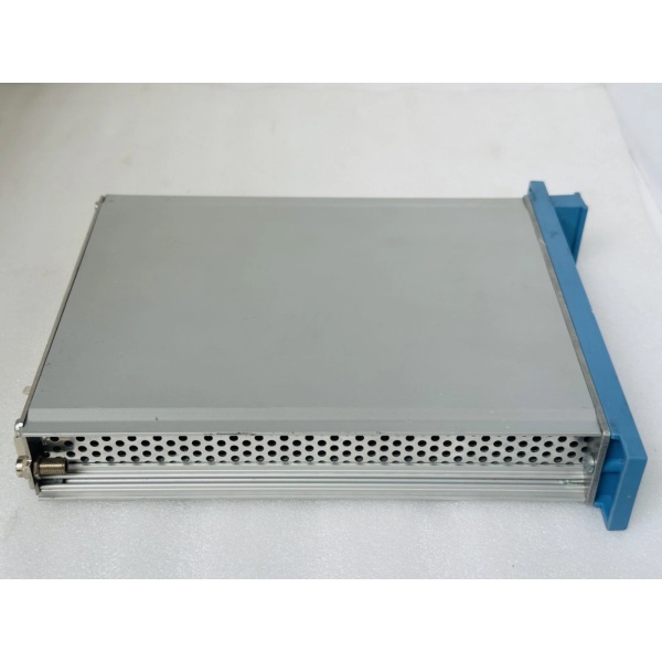
Honeywell FC-USI-0002
The Real-World Problem It Solves
Boilers need reliable temperature control to prevent overheating and ensure efficient operation. A mechanical thermostat or simple on/off control can’t provide the fine adjustment or safety protection required for commercial and industrial hydronic systems. The L404F1235/U combines immersion temperature control with a manual reset high-limit safety switch. It maintains boiler water temperature within the setpoint differential and automatically shuts down the burner if the temperature exceeds the high-limit setpoint—preventing dangerous overpressure conditions or boiler damage.
Where you’ll typically find it:
- Commercial hydronic boilers controlling supply water temperature
- Industrial boiler houses providing temperature regulation and high-limit safety
- Hot water systems requiring immersion temperature control with manual reset safety
Bottom line: It’s a simple mechanical workhorse that’s kept boilers from overheating for decades—no microcontrollers, no batteries, just reliable physics.
Hardware Architecture & Under-the-Hood Logic
The L404F1235/U is a mechanical immersion temperature controller that uses a filled bulb and capillary system to sense water temperature directly. No electronics, no power supply required—the physics of thermal expansion drives the switching logic. It features a single-stage control switch (SPDT) for burner on/off control and a separate high-limit switch that opens on overtemperature and requires manual reset before operation can resume.
-
Temperature Sensing: The immersion bulb contains a temperature-sensitive fluid (typically a wax or gas mixture) that expands when heated. This expansion travels through the capillary tube to a bellows or diaphragm in the controller housing. The pressure from the expanding fluid exerts force on the switch mechanism, proportional to the water temperature sensed by the bulb.
-
Main Control Switch: The primary temperature setpoint is adjusted via a dial on the front of the controller. This dial sets the spring tension that the bellows must overcome to trip the switch. When water temperature rises above the setpoint minus the differential setting, the SPDT switch opens (breaks the burner circuit). When temperature drops below the setpoint minus the differential, the switch closes (completes the burner circuit). The differential (deadband) is adjustable via a separate knob, preventing rapid cycling.
-
High-Limit Safety Switch: A separate temperature sensing path (same bulb with independent mechanism) monitors for overtemperature conditions. If the water temperature exceeds the high-limit setpoint (typically 200–250°F), the high-limit switch trips open and latches mechanically. The burner circuit is interrupted and cannot be reset until the manual reset button on the controller is pressed—this prevents automatic restart after overtemperature, ensuring the operator is aware of the safety trip.
-
Manual Reset Latching Mechanism: The high-limit switch uses a mechanical latch that holds the switch in the tripped (open) position even after the temperature returns below the high-limit setpoint. Only manual intervention (pressing the reset button) releases the latch and allows the high-limit switch to close again. This design ensures that an overtemperature condition isn’t silently ignored.
-
SPDT Switch Configuration: Both the main control and high-limit switches are SPDT (Single Pole, Double Throw), providing both normally-open (NO) and normally-closed (NC) contacts. This wiring flexibility allows series or parallel connection with other safety devices, multiple burner staging, or interlocking with other controls (e.g., low-water cutoff).
Honeywell FC-USI-0002
Field Service Pitfalls: What Rookies Get Wrong
Improper Bulb Installation Depth
I’ve seen techs screw the immersion bulb into a well but not seat it fully against the bottom. Air gap between the bulb tip and the well bottom causes thermal lag—the bulb senses ambient air in the well, not actual water temperature. The controller thinks the boiler is cooler than it actually is, running the burner too long and causing high-limit trips or uneven heating.
- Field Rule: Always use thermal paste (high-temperature heat sink compound) on the bulb before insertion. Ensure the bulb is fully seated at the bottom of the thermowell with no air gaps. Measure insertion depth against the well length—bulb should touch bottom. If the well is too long, use a bulb with a longer immersion length or replace the well.
Mounting with Capillary Bent Too Sharply
New engineers try to force the capillary tube around tight corners or kink it to fit the enclosure layout. Sharp bends restrict fluid flow in the capillary, causing sluggish response time or complete failure to sense temperature changes. Once kinked, the capillary is permanently damaged—the controller needs replacement.
- Quick Fix: Follow the minimum bend radius specification (typically 3–4 times the capillary diameter, about 1–1.5 inches). Never bend the capillary within 2 inches of the bulb or controller connection. Route the capillary away from heat sources, vibration, and pinch points. If routing is impossible without sharp bends, consider relocating the controller or using a remote bulb version with longer capillary.
Setting Differential Too Tight for the Application
Default differential is typically 10–15°F, which works for most boilers. Rookies crank it down to 5°F trying to get tighter temperature control. The result: burner short-cycles every few minutes, causing premature wear on the burner ignition system, thermal stress on the boiler, and poor efficiency. If differential is too wide (>25°F), temperature swings become noticeable to occupants, and the boiler takes too long to recover.
- Field Rule: Set differential based on system thermal mass and usage patterns. For large boilers with high thermal inertia (cast iron, large volume), use 15–25°F differential to prevent short-cycling. For smaller boilers or systems requiring tight temperature control, 8–12°F is adequate. Monitor cycle count over 24 hours—if burner cycles more than 6 times per hour, increase differential.
Wiring High-Limit in Parallel with Main Control
I’ve seen installations where the high-limit and main control switches are wired in parallel (both NO contacts feeding burner). If the main control is satisfied (open) but the high-limit trips, the burner stays on because the high-limit contact doesn’t interrupt the circuit—defeating the purpose of the safety. The high-limit must be in series with the main control to actually shut down the burner on overtemperature.
- Field Rule: Wire the high-limit switch in series with the main control switch and other safety devices (low-water cutoff, pressuretrol). Use the NC (normally-closed) contacts on both switches so any fault (open contact) removes power from the burner. Verify with a multimeter: when both switches are closed (normal operation), continuity exists through the series chain. When either opens, continuity is broken.
Forgetting to Test High-Limit Reset Function
Techs install the L404F1235/U, verify main control operation, and assume high-limit works because it’s “mechanical.” They never actually trip it to confirm manual reset latching. Months later, a real overtemperature occurs, the high-limit trips, and then auto-resets due to a faulty latch—the boiler restarts automatically without operator intervention, potentially repeating the overtemperature cycle.
- Field Rule: During commissioning and annual maintenance, perform a controlled high-limit test: raise boiler temperature manually or using a heat gun on the bulb until the high-limit trips. Verify the burner 终止s. Let temperature cool below high-limit, then attempt to restart—the burner should NOT start until the manual reset button is pressed. Document the test in maintenance logs. If the high-limit auto-resets, replace the controller immediately.
Ignoring Ambient Temperature Effects on Controller Location
Rookies mount the L404F1235/U in a location exposed to high ambient heat (direct sunlight, near hot pipes, in a non-ventilated boiler room). The controller housing absorbs ambient heat, affecting the internal mechanisms. The controller may trip prematurely or fail to accurately sense the bulb temperature because the housing itself is overheated.
- Quick Fix: Mount the controller in a location with ambient temperature below 100°F (38°C). If mounting near the boiler is unavoidable, use a shield or install the controller in a ventilated enclosure. Verify ambient temperature at the mounting location with a thermometer during peak operation. If ambient exceeds spec, relocate the controller or provide cooling.
Commercial Availability & Pricing Note
Please note: The listed price is for reference only and is not binding. Final pricing and terms are subject to negotiation based on current market conditions and availability.


