
Description
Hard-Numbers: Technical Specifications
- Channel Count: 16 digital input channels
- Input Types Supported:
- Dry contact (switch input)
- 24VDC wetting voltage
- NAMUR sensor compatible
- 2-wire transmitter
- Input Voltage: 24VDC nominal (range 18–32VDC)
- Input Current per Channel: 8–15 mA typical
- Response Time: <10 ms typical for digital inputs
- Diagnostic Coverage: >99% per IEC 61508 (SIL 3)
- Isolation: Channel-to-bus: 1500VAC; Channel-to-channel: 500VAC typical
- Operating Temperature: -20°C to +60°C full load; -40°C to +70°C derated
- Storage Temperature: -40°C to +85°C
- Humidity: 10–90% RH non-condensing
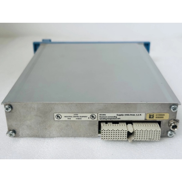
- Power Consumption: 3–5W typical (varies with channel count)
- Certifications: TÜV SIL 3 per IEC 61508, IEC 61511; UL/cUL Class I Div 2; CE; ATEX (varies by revision)
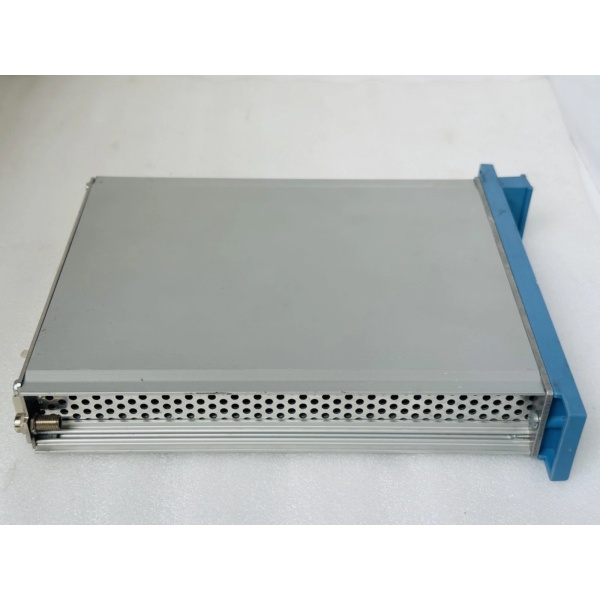
- Dimensions: 191 mm × 188 mm × 65 mm (7.5″ × 7.4″ × 2.6″)
- Mounting: Hot-swappable in Safety Manager I/O chassis
Honeywell FC-USI-0002
The Real-World Problem It Solves
Safety systems need to reliably read discrete status signals—limit switches, pressure switches, valve position feedback—and those signals can’t be ambiguous or corrupted. A non-safety digital input module might read a noisy contact as multiple state changes or miss a trip signal entirely due to inadequate filtering or lack of diagnostics. The FC-USI-0002 provides SIL 3 certified digital input channels with debounce filtering, wetting voltage, and comprehensive diagnostics that detect wire breaks, shorts, and stuck-at faults. When a safety-critical contact signals an ESD condition, this module reads it accurately and reports it to the controller without doubt.
Where you’ll typically find it:
- Safety Manager ESD cabinets reading emergency 终止 buttons, pressure switches, and valve position feedback
- HIPPS systems with redundant valve position switches requiring high-integrity status acquisition
- Fire & gas systems with discrete detector inputs (flame detectors, smoke detectors) requiring SIL 3 compliance
Bottom line: When the ESD button gets pressed or the pressure switch trips, the FC-USI-0002 makes sure the Safety Manager actually sees it—no ambiguity, no missed trips.
Hardware Architecture & Under-the-Hood Logic
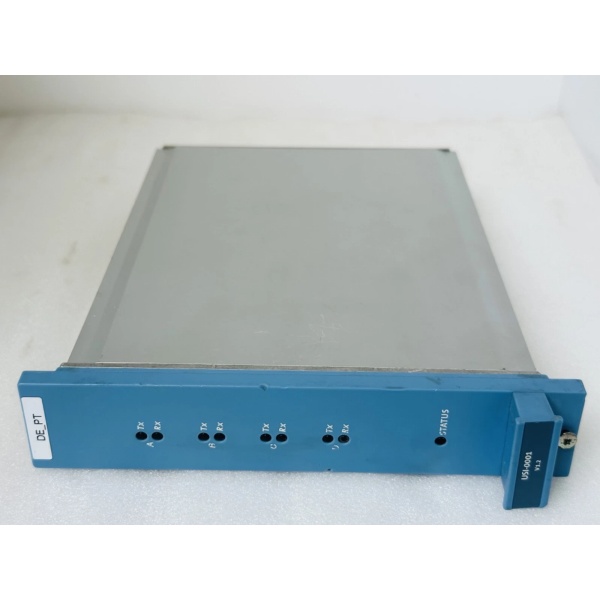
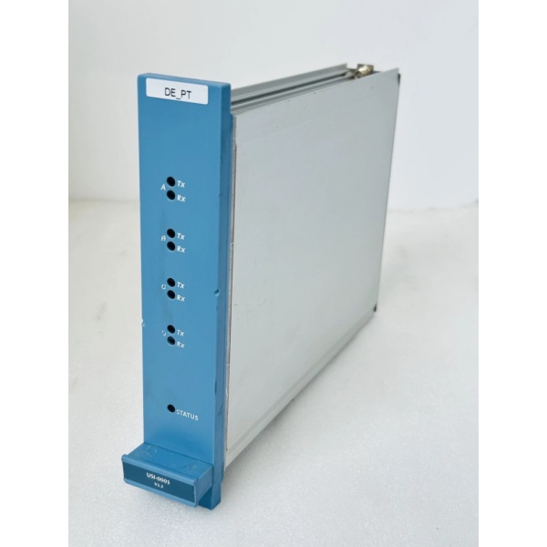
The FC-USI-0002 is a universal safety input module designed for the Honeywell Safety Manager platform. It slides into the I/O chassis and communicates via the SafetyNet fieldbus to the Safety Manager controller. Inside, it features dual redundant processing chains (A and B) that independently read and validate each input channel for SIL 3 compliance. Each of the 16 channels has configurable debounce filtering, wetting voltage generation, and diagnostic circuitry that continuously monitors input integrity.
-
Input Signal Conditioning: Each channel starts with an EMI/RFI filter stage that suppresses noise picked up on field wiring. A configurable debounce filter (typically 2–10 ms) rejects contact bounce and transient spikes. For dry contact inputs, the module generates a wetting voltage (24VDC) to ensure reliable contact sensing. NAMUR sensor inputs get the proper current-limiting and threshold detection per EN 50227.
-
Dual Redundant Processing: Both Chain A and Chain B independently read each input channel simultaneously. The two chains compare results via internal cross-checking logic. If Chain A reads “ON” and Chain B reads “OFF” or states diverge, a fault is flagged immediately. This lockstep comparison provides the >99% diagnostic coverage required for SIL 3.
-
Diagnostic Engine: The module continuously runs channel-level diagnostics:
- Wire break detection (open circuit)
- Short circuit detection (line-to-ground or line-to-line)
- Stuck-at-0 / stuck-at-1 detection
- Wetting voltage monitoring
- Overcurrent detection on each channelFaults are reported to the Safety Manager controller via the SafetyNet fieldbus. The controller then takes predefined action: alarm operators, bypass faulty channels while keeping healthy ones running, or initiate safe state if critical inputs fail.
-
Hot-Swap Capability: In redundant configurations, one FC-USI-0002 can be physically removed while the system stays online. The surviving module maintains safety function during the swap. When the new module is inserted, it automatically syncs configuration and state with the controller. The Safety Manager handles switchover without operator intervention.
-
Isolation and Surge Protection: Each channel provides galvanic isolation between field circuits and the module’s internal logic (1500VAC rating). Surge protection per IEC 61000-4-5 protects against voltage spikes from long cable runs and lightning-induced transients. This is critical in offshore platforms and refineries where EMI and surges are common.
Honeywell FC-USI-0002
Field Service Pitfalls: What Rookies Get Wrong
Mixing Dry Contact and NAMUR Sensors on the Same Module
New engineers see “universal input” and start wiring dry contact limit switches next to NAMUR proximity sensors on the same module. The issue: NAMUR sensors require specific current limiting and threshold detection, while dry contacts need wetting voltage. If channels aren’t configured correctly in the Safety Manager project, NAMUR sensors won’t be detected properly, or dry contacts won’t get reliable wetting current—leading to intermittent readings or missed trips.
- Field Rule: Group input types by module where possible. Keep dry contact inputs on one module, NAMUR sensors on another. If mixed types are unavoidable, verify each channel’s configuration in the Safety Manager engineering environment matches the actual field device type. Never assume “universal” means “plug anything anywhere.”
Ignoring Wire Break Diagnostics on Normally-Closed Safety Contacts
Safety contacts (ESD buttons, pressure switches) are typically wired normally-closed so a wire break is detected as an alarm. Rookies configure these as normally-open in the Safety Manager project. When a wire breaks or the contact fails open, the controller reads “OFF” as normal operation instead of a fault—the safety function is silently compromised until a real trip is missed.
- Field Rule: For safety-critical discrete inputs, verify the fail-safe state: wire the contact normally-closed for alarm/fault detection. Configure the channel as normally-closed in the Safety Manager project. Test by opening the field contact—the controller should read an alarm condition, not a normal state. Document the expected state in loop sheets.
Using Undersized Field Wiring for Long Cable Runs
Techs use 18 AWG wire for field wiring because “it fits in the terminal block.” For long cable runs (>50m) to remote limit switches, 18 AWG has too much resistance, causing voltage drop that affects wetting voltage delivery. The module can’t reliably detect contact state, leading to intermittent readings or false alarms. In worst cases, wetting voltage drops below the threshold for NAMUR sensors, rendering them inoperable.
- Quick Fix: Calculate voltage drop for the worst-case cable length and input current. Use 14 AWG or 16 AWG wire for runs >30m to ensure wetting voltage stays within 18–32VDC at the field device. Measure voltage at the field device terminal during commissioning—should be 24VDC ±10%. Don’t guess wire size—calculate it.
Forgetting to Test Wire Break Detection
Rookies install and configure FC-USI-0002 modules but never verify wire break diagnostics actually work. They assume “no fault” means everything is fine. When a wire breaks months later, the module might not detect it because the diagnostic wasn’t enabled or configured correctly. The safety function runs blind until a real event exposes the missing diagnostic.
- Field Rule: During commissioning, perform a wire break test on each critical input channel: disconnect the field wire at the terminal block and verify the Safety Manager controller detects the open circuit as a fault alarm. Document the test results. If wire break detection doesn’t work, check channel configuration and terminal connections before putting the system online.
Overlooking Debounce Time Configuration
Default debounce time on FC-USI-0002 is typically 2–5 ms, which works for most applications. However, some mechanical limit switches have significant bounce (up to 20 ms). If debounce time is too short, the module reads multiple state changes from a single contact closure—causing spurious counts in the logic or triggering unintended actions. If debounce is too long, fast trip signals might be missed entirely.
- Quick Fix: Verify the mechanical characteristics of field contacts (bounce time) and configure debounce accordingly. Test with an oscilloscope or event logger during commissioning: close the contact and verify only one state change is registered in the Safety Manager event log. Adjust debounce until you get clean, single-state detection for each contact closure.
Commercial Availability & Pricing Note
Please note: The listed price is for reference only and is not binding. Final pricing and terms are subject to negotiation based on current market conditions and availability.


