
Description
Hard-Numbers: Technical Specifications
- Function: Redundant link switching for SafetyNet / fieldbus networks
- Network Type: SafetyNet redundant fieldbus (Honeywell proprietary protocol)
- Port Configuration:
- 4 network ports (typically labeled Network A In/Out, Network B In/Out)
- Supports redundant ring or star topology
- Data Rate: 10/100 Mbps Ethernet (SafetyNet over Ethernet)
- Redundancy Type: Active-standby switching with automatic failover
- Switching Time: <10 ms typical failover detection and switchover
- Isolation: 1500VAC isolation between network ports and internal logic
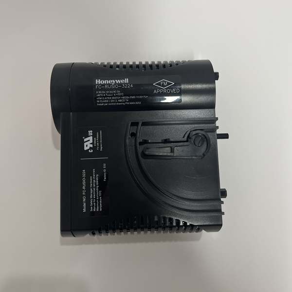
- Operating Temperature: -20°C to +60°C full load; -40°C to +70°C derated
- Storage Temperature: -40°C to +85°C
- Humidity: 10–90% RH non-condensing
- Power Consumption: 3–5W typical
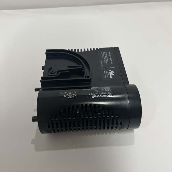
- Certifications: TÜV SIL 3 per IEC 61508, IEC 61511; UL/cUL Class I Div 2; CE; ATEX (varies by revision)
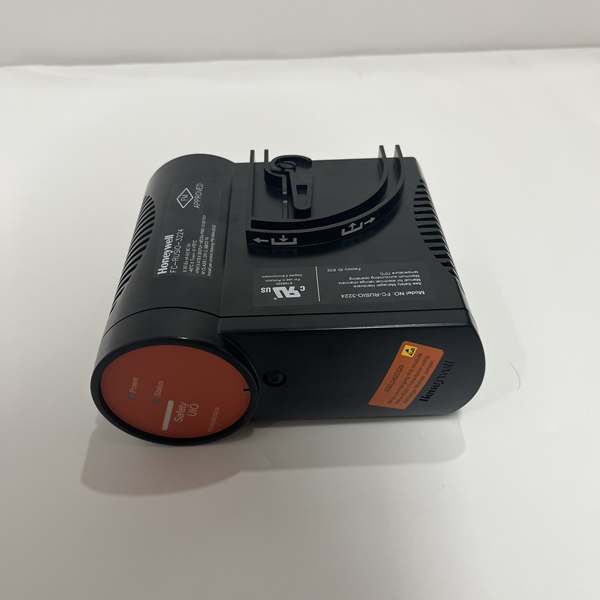
- Dimensions: 191 mm × 188 mm × 65 mm (7.5″ × 7.4″ × 2.6″)
- Mounting: Hot-swappable in Safety Manager I/O chassis
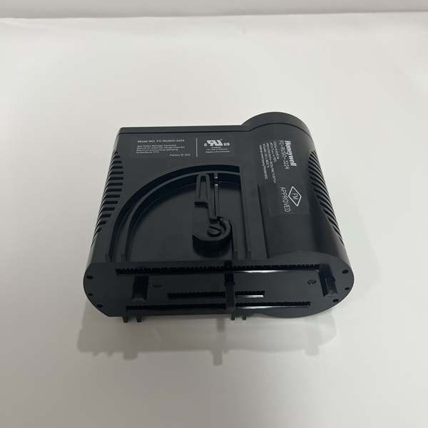
Honeywell FC-RUSIO-3224
The Real-World Problem It Solves
Safety Manager networks can’t afford single-point failures in the communication path. If a single cable gets cut, a switch fails, or a network segment goes dark, I/O modules lose communication with the controller and the safety function either spurious-trips or goes blind. The FC-RUSLS-3224 sits between the Safety Manager controller and the I/O network, providing redundant network paths with automatic switching. When the primary path fails, the module detects the loss and switches to the backup path in milliseconds—no operator intervention, no safety function interruption.
Where you’ll typically find it:
- Safety Manager cabinets requiring redundant SafetyNet connections between controllers and remote I/O chassis
- SIL 3 ESD systems where network cable runs are long or pass through hazardous areas (offshore platforms, classified zones)
- Distributed Safety Manager architectures with multiple I/O chassis connected via ring topology for maximum redundancy
Bottom line: Your network cables will fail—plan for it. The FC-RUSLS-3224 ensures a single cable cut or switch failure doesn’t take your safety system offline.
Hardware Architecture & Under-the-Hood Logic
The FC-RUSLS-3224 is a redundant link switch module designed for the Honeywell Safety Manager platform. It slides into the I/O chassis and acts as a network redundancy bridge between the Safety Manager controller and the I/O network. Inside, it features dual network interface controllers (NICs) and switching logic that continuously monitors network health on both paths. When the active path fails, the module automatically switches traffic to the standby path without disrupting I/O communication.
-
Dual Network Interface Paths: The module contains two independent network controllers—one for Network A and one for Network B. Each path has its own physical network ports (In/Out) and communication logic. Both paths are powered and active simultaneously, with one designated as primary and the other as standby. The controller monitors both paths for heartbeat signals and data integrity.
-
Continuous Health Monitoring: The module continuously polls both network paths for:
- Link status (physical connection detection)
- Heartbeat packets from Safety Manager controller
- Error rates and CRC failures
- Communication latency and timeout detectionIf any parameter on the primary path exceeds thresholds (e.g., lost heartbeat, high error rate), the module initiates failover.
-
Automatic Failover Logic: When the primary path is deemed unhealthy, the module switches traffic to the standby path in <10 ms. The switch is transparent to the Safety Manager controller and I/O modules—they continue communicating without reconfiguration. The module generates an alarm to notify operators of the failover event. The failed path is flagged for maintenance while the backup path maintains full safety function.
-
Redundant Power and Logic: The module has dual internal power supplies fed from the Safety Manager backplane. If one power rail fails, the other keeps the module operational. Internal logic is duplicated for SIL 3 compliance—critical decisions (like failover initiation) are validated by redundant processing chains before execution.
-
Diagnostic and Status Reporting: Front-panel LEDs indicate network status on both paths (green = healthy, yellow = degraded, red = fault). The module continuously reports status to the Safety Manager controller via the backplane, allowing operators to monitor network health in real-time. Events (failover, recovery, faults) are logged in the controller event history for troubleshooting and maintenance planning.
Honeywell FC-RUSIO-3224
Field Service Pitfalls: What Rookies Get Wrong
Plugging Both Network Paths into the Same Switch
I’ve seen techs run both Network A and Network B cables to the same network switch or daisy-chain them through a single device. If that switch fails, both redundant paths go dead simultaneously—the I/O network goes down, and the safety function enters failsafe state. The redundancy is an illusion when the physical network isn’t truly independent.
- Field Rule: Verify that Network A and Network B are on physically separate network paths with independent switches or media. In ring topology, ensure the ring is broken at only one point—don’t create two breaks that isolate segments. Test live failover by pulling Network A while monitoring the Safety Manager diagnostics to confirm Network B maintains communication.
Ignoring LED Status Until the Alarm Sounds
New engineers assume “no alarm = no problem” and ignore the front-panel LED indicators on the FC-RUSLS-3224. They don’t notice the yellow “degraded” LED indicating Network A has high error rates or intermittent packet loss. The backup path is carrying more load than designed, and when it finally fails, there’s no fallback—both paths are already compromised.
- Quick Fix: During routine rounds, check the front-panel LEDs on all link switch modules. A yellow LED means one path is degraded—investigate immediately (check cables, switches, connectors). Don’t wait for a red fault LED. Preventive maintenance beats emergency downtime every time.
Never Testing Failover During Commissioning
Techs install the FC-RUSLS-3224, verify both paths are connected, and assume redundancy works. They never actually pull the primary cable to confirm failover happens. Months later, a real failure occurs and switchover doesn’t work—either the module wasn’t configured correctly, or the standby path was never properly synced. The safety system goes offline when it should have survived.
- Field Rule: Perform a controlled failover test during commissioning or scheduled outage: disconnect Network A and verify the Safety Manager controller maintains communication with all I/O modules via Network B without spurious alarms. Document failover time and any transient faults. Repeat the test annually or after any network changes.
Overlooking Cable Length Limits in Ring Topology
In large facilities with distributed I/O chassis, techs sometimes run ring topologies that exceed the Ethernet segment length limits (100m for Cat5e/Cat6 copper). Signal degradation causes intermittent packet loss, high error rates, and eventually network timeouts. The link switch constantly flips between paths, creating unpredictable behavior that’s a nightmare to troubleshoot.
- Quick Fix: Calculate total cable length between the controller and the furthest I/O chassis in the ring. If >100m for copper, use fiber media converters or install intermediate switches with fiber uplinks. Verify signal integrity with a network tester during installation. Don’t guess cable length—measure it.
Mixing Cable Types or Using Incorrect Shielding
Rookies run SafetyNet network cables right next to VFD output cables or 480V power lines without proper separation or shielding. EMI induces noise and bit errors, causing the link switch to constantly switch paths or generate false alarms. In worst cases, communication becomes unreliable enough to trigger safety function degradation.
- Field Rule: Follow Honeywell cable routing guidelines: keep network cables at least 300mm (12″) away from power cables, cross them at 90° angles if they must intersect, and use shielded twisted-pair cables with proper shield termination (single-point ground at one end). Test for EMI with a portable spectrum analyzer if the environment is particularly noisy.
Commercial Availability & Pricing Note
Please note: The listed price is for reference only and is not binding. Final pricing and terms are subject to negotiation based on current market conditions and availability.


