
Description
Hard-Numbers: Technical Specifications
- Total Channels: 8 configurable channels
- Channel Configurations (per channel, software-selectable):
- Analog Input (AI): 4–20 mA / 0–10 V
- Analog Output (AO): 4–20 mA / 0–10 V
- Digital Input (DI): 24 VDC dry contact or proximity
- Digital Output (DO): 24 VDC solid-state or relay (verify per channel type)
- Analog Resolution: 16-bit ADC (AI), 16-bit DAC (AO)
- Digital I/O Voltage Range: 0–24 VDC (logic levels: <5V = OFF, >10V = ON)
- HART Support: Yes on AI/AO channels (pass-through for smart field devices)
- Isolation: 1500V channel-to-channel, channel-to-backplane (verify per configuration)
- Update Rate: 50–500 ms (configurable per channel type)
- Accuracy: ±0.1% of span (AI/AO at 23°C ± 2°C)
- Operating Temperature: 0°C to +60°C
- Power Consumption: ~350 mA @ 24 VDC (backplane powered)
- Backplane Communication: Experion Series-C I/O bus to C300 controller
- Protection: Reverse polarity, overvoltage, ESD per IEC 61000-4-2
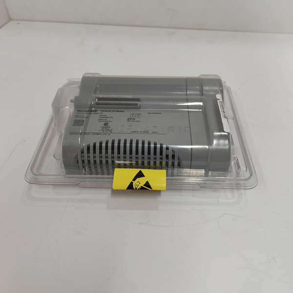
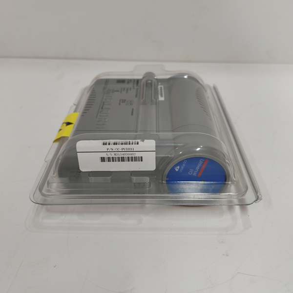
Honeywell CC-PUIO31
The Real-World Problem It Solves
Control cabinets run out of space fast. You’ve got a mix of analog pressure transmitters, 4–20mA control valves, limit switches, and solenoid valves, and every different signal type usually requires its own dedicated module. The CC-PUIO31 lets you configure each of its 8 channels as AI, AO, DI, or DO on the fly, so you’re not wasting slots on half-empty cards. This matters when you’re retrofitting an old DCS or adding field devices to a packed rack where you can’t justify installing a dedicated 16-channel analog input just to hook up one extra transmitter.
Where you’ll typically find it:
- Retrofit projects in older Experion PKS installations where cabinet space is at a premium and mixed I/O types are needed
- Remote I/O cabinets with limited footprint requiring flexible signal conditioning for skid-mounted equipment
- Pilot plant or test installations where I/O requirements change frequently and reconfigurability saves hardware costs
Bottom line: This module is your Swiss Army knife—don’t dedicate entire cards to single signal types when you can mix analog and digital on one module and reclaim rack slots.
Hardware Architecture & Under-the-Hood Logic
The CC-PUIO31 slides into the Experion Series-C IOTA backplane and pulls 24VDC from the bus. Inside, it’s a hybrid design—each of the 8 channels has both analog and digital signal paths, with configuration switches or software settings determining which path is active. Analog channels use 16-bit ADC/DAC circuits with HART modem integration for smart field devices. Digital channels use opto-isolated input/output drivers with configurable debounce filters. The module multiplexes all 8 channels and ships data to the C300 over the Series-C I/O bus.
- Channel Configuration Logic: Each channel’s mode (AI/AO/DI/DO) is set via Experion PKS configuration software. This routes the terminal signal through the appropriate conditioning circuit—ADC for analog input, DAC for analog output, or digital I/O buffers for discrete signals.
- Analog Input Path (AI mode): 4–20mA or 0–10V signals pass through input conditioning (filtering, scaling), hit a 16-bit ADC, and digitize for the C300. HART modems overlay FSK tones for smart instrument communication if enabled.
- Analog Output Path (AO mode): The C300 writes setpoints to the module’s 16-bit DAC, which drives 4–20mA or 0–10V outputs. Output circuits include current limiting and fault detection for open-circuit or short-circuit conditions.
- Digital Input Path (DI mode): 24VDC signals from dry contacts or proximity switches pass through opto-isolation and debounce filters (software-selectable). The module reads logic state and ships status to the C300.
- Digital Output Path (DO mode): The C300 writes logic states to the module’s output drivers, which switch 24VDC loads (solenoids, indicator lights, relays). Solid-state outputs offer high-speed switching; verify if relay outputs are available on your hardware revision.
- Backplane Data Transfer: All channel data—AI readings, AO feedback, DI states, DO status—packs up and heads over the Series-C I/O bus to the C300. The C300 reads/writes at its configured scan rate, independent of the module’s internal processing speed.
Honeywell CC-PUIO31
Field Service Pitfalls: What Rookies Get Wrong
Assuming All Channels Are Identical
Techs pull a CC-PUIO31 replacement from stores, swap it in, and wire it exactly like the old one. Problem is, the previous config had Channel 1 as AO driving a control valve, and the replacement came defaulted to AI. The valve slams shut or runs wide open because the module’s expecting a 4–20mA input instead of driving an output.
- Field Rule: Always back up the channel configuration before swapping. In Experion PKS, export the I/O configuration for the module and reload it onto the replacement. Don’t trust factory defaults—verify each channel’s mode matches the field wiring.
Mixing Voltage and Current Outputs Without Calibration
I’ve seen engineers reconfigure a channel from 4–20mA current output to 0–10V output for a VFD speed reference without recalibrating. The DAC scaling is off, and the VFD runs at 60% speed when the setpoint commands 100%. Production drifts for hours before anyone notices.
- Field Rule: After changing channel modes, perform a calibration check. Apply known input values (4mA, 12mA, 20mA or 0V, 5V, 10V) and verify output matches with a multimeter. Don’t assume software scaling aligns with hardware reality.
Overloading Digital Outputs with Inductive Loads
Rookies wire 24VDC solenoid valves directly to digital outputs without flyback diodes. When the output switches off, inductive kickback spikes back into the module, eventually frying the output driver or causing erratic behavior on adjacent channels.
- Field Rule: Use external relays or install flyback diodes across inductive loads (solenoids, motor starters, contactors). If you must drive inductive loads directly, verify the CC-PUIO31’s DO ratings include inductive kickback protection—most don’t.
Ignoring HART Address Conflicts on Mixed AI/AO Configurations
Channels configured as AI with HART pass-through need unique HART device addresses. I’ve seen engineers set all transmitters to address “0” (polling mode) or duplicate addresses, causing communication timeouts or reading the wrong device’s PV.
- Field Rule: Assign unique HART addresses to each smart instrument (typically 1–15, with 0 reserved for burst mode). Use a HART communicator to verify address settings before commissioning. Don’t rely on “it worked before”—address conflicts are silent killers.
Grounding Analog and Digital Returns to Different Points
Techs ground analog signal returns to the cabinet earth and digital commons to a different bus bar. The CC-PUIO31 sees a potential difference between analog and digital grounds, causing offset errors on AI channels or erratic DI/DO behavior due to ground loops.
- Quick Fix: Bond all commons—AI return, AO return, DI common, DO common—to a single clean ground point in the cabinet. Use isolated barriers if field devices require separate grounding schemes. Never mix chassis ground and signal ground without verifying isolation ratings.
Commercial Availability & Pricing Note
Please note: The listed price is for reference only and is not binding. Final pricing and terms are subject to negotiation based on current market conditions and availability.


