

Description
Hard-Numbers: Technical Specifications
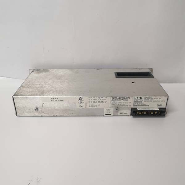
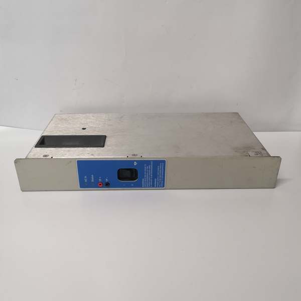
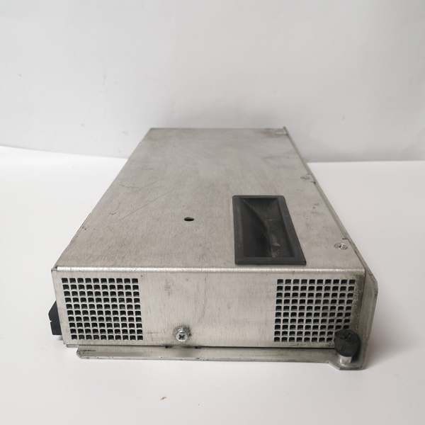
- Module Type: TDI Redundant Power Supply Unit
- Input Voltage Range: 100-240 VAC (85-265 VAC wide range)
- Input Frequency: 47-63 Hz
- Input Current: 10 A maximum
- Output Voltage: 24-26 VDC (nominal 24 VDC)
- Output Current: 20 A maximum
- Rated Power: 480W nominal (some sources cite 100W-500W depending on configuration)
- Efficiency: >90%
- Redundancy: Dual redundant design (supports parallel operation with load sharing)
- Hot Swap: Supports hot-plug replacement without system shutdown
- Operating Temperature: -10°C to +60°C (some sources cite -20°C to +70°C)
- Storage Temperature: -40°C to +85°C
- Protection Rating: Class I, Division 2, Zone 2 (hazardous area certified)
- Isolation: Input-to-output isolation per IEC 60950
- Protections: Overload, overvoltage, short-circuit, over-temperature protection
- Dimensions: 5 cm × 16.5 cm × 34.2 cm (varies by exact revision)
- Weight: 2.14 kg (some sources cite 4.75 lbs / 2.16 kg)
- Country of Origin: China (manufactured by Transistor Devices Inc. for Honeywell)
- Mounting: Slide-in rack mounting for TDC 3000 cabinets
- MTBF: Typically >100,000 hours at 40°C ambient
- Regulatory Approvals: UL, CE, cULus, ATEX (for hazardous areas)
Honeywell 51199929-100
The Real-World Problem It Solves
Process control systems run 24/7 in refineries, chemical plants, and power stations. A single power supply failure takes down the entire DCS—your process drifts, safety systems shut down, and you’re staring at millions in lost production every hour. The 51199929-100 provides redundant 24VDC power through dual hot-swappable modules. If one fails, the other keeps the rack alive while you swap out the bad unit without hitting an ESD.
Where you’ll typically find it:
- Honeywell TDC 3000 DCS controller cabinets in refineries and petrochemical plants
- Safety Instrumented Systems (SIS) and Emergency Shutdown (ESD) racks
- Hazardous area installations (Class I Div 2 Zone 2) in oil and gas facilities
Bottom line: This module is your insurance policy against power-related downtime—redundant, hot-swappable, and certified for explosive atmospheres.
Hardware Architecture & Under-the-Hood Logic
The 51199929-100 is a switching power supply designed for TDC 3000 racks. It’s not just a transformer—it’s an intelligent power conditioner with active PFC, current sharing, and protection circuits.
-
AC Input Stage: Line voltage (100-240 VAC) enters through EMI filtering. Power factor correction (PFC) circuitry minimizes harmonic distortion and maximizes efficiency. The input bridge rectifier converts AC to rough DC.
-
DC/DC Conversion Stage: High-frequency switching (typically 50-100 kHz) converts the rough DC to an isolated intermediate bus voltage. A transformer provides galvanic isolation between input and output, protecting downstream equipment from line transients.
-
Output Regulation: Output MOSFETs switch at high frequency through inductors to generate regulated 24-26 VDC. PWM control maintains constant voltage despite input fluctuations and load changes. The output stage uses parallel MOSFETs for 20A capacity with current sharing across redundant modules.
-
Current Sharing Circuit: When operating in redundant mode, active current sharing ensures each module contributes proportionally to the load. If one module drifts or fails, the other compensates instantly without a voltage sag that could crash the controller.
-
Protection Logic: Continuous monitoring of output voltage, current, and temperature triggers protective shutdowns:
- Overload: Current exceeds 22A for >5 seconds
- Overvoltage: Output exceeds 30 VDC
- Short-circuit: Instantaneous current limit at 25A
- Over-temperature: Internal heatsink >85°C
-
Hot-Swap Control: Backplane connectors use make-before-break sequencing. When you pull a module, output contacts disconnect before power pins separate, preventing backfeed into a live module. Insertion reverses the sequence—power makes first, then output connects.
-
Diagnostics: Front panel LEDs indicate health (Power OK, Fault, Load Sharing). Internal monitoring circuits feed fault codes to the TDC 3000 system via the backplane, alerting operators to degraded conditions before complete failure.
Honeywell 51199929-100
Field Service Pitfalls: What Rookies Get Wrong
Hot-Swapping Without Verifying Redundancy
I’ve seen techs pull a live power module thinking redundancy will cover them, only to find the second unit was already failed or removed. The whole rack drops dead mid-process, triggering an ESD and safety shutdown.
- Field Rule: Before hot-swapping, verify the redundant module is healthy and carrying load. Check both module LEDs and the TDC 3000 system diagnostics. Never pull a module if it’s the last one running.
Ignoring Load Balancing
Installers throw in two modules and assume redundancy is automatic. If one module carries 18A and the other only 2A, the loaded unit runs hot and fails early. The second unit can’t pick up the full 20A load when the primary dies.
- Quick Fix: Check current sharing LEDs or use a clamp meter on output terminals. Both modules should share the load within 20% of each other. If not, the load sharing circuit is bad—replace the unbalanced module.
Overlooking Hazardous Area Certification
Techs install non-certified replacements in Zone 2 classified areas, assuming “24VDC is low voltage.” The inspection fails, and you’re tearing out a live system to swap in compliant hardware.
- Field Rule: Verify the 51199929-100 replacement carries Class I Division 2 Zone 2 certification (ATEX/IECEx). Check the label—no certification marks means it’s illegal for hazardous locations, regardless of voltage rating.
Improper Grounding of the Module
New guys bolt the module to the rack but skip the dedicated chassis ground screw. Without proper grounding, the module’s protection circuits won’t clear faults correctly, and EMI can crash adjacent cards.
- Quick Fix: Use the dedicated grounding stud or screw on the module chassis. Bond it to the cabinet ground bus with a star washer. Don’t rely on the rack rails alone for grounding.
Running Modules at Ambient Temperature Limits
Control rooms hit 55-60°C in summer, and the power modules are stacked with zero clearance. The thermal protection trips randomly, causing intermittent shutdowns that look like logic faults.
- Field Rule: Maintain at least 1U (4.45 cm) vertical clearance above and below power modules. Verify cabinet ventilation—fans running, filters clean. If ambient exceeds 50°C, derate the output current by 2% per degree Celsius above 50°C per the datasheet.
Neglecting to Verify Output Voltage Under Load
Techs measure 24.2 VDC at the terminals with no load and call it good. When 20A of field devices kick in, voltage sags to 21V and TDC 3000 controllers start acting erratic.
- Field Rule: Load test the output. With the system running, measure voltage at the module terminals and at the farthest point on the backplane. Voltage drop shouldn’t exceed 0.5 V from source to load. If it’s sagging more, check for loose connections or undersized wiring.
Forgetting to Check Input Phase Rotation
Some three-phase input variants care about phase sequence, though the 51199929-100 is mostly single-phase. However, I’ve seen techs feed 277V or 480V into the 100-240 VAC input “to be safe.”
- Quick Fix: Verify input voltage before applying power. Use a multimeter on the line side—100-240 VAC only. Feeding higher voltage fries the input stage instantly, and there’s no repair for that damage.
Please note: The listed price is for reference only and is not binding. Final pricing and terms are subject to negotiation based on current market conditions and availability.

