
Description
Hard-Numbers: Technical Specifications
- Module Type: Digital Output (DO) – Relay
- Output Channels: 8 relay output channels
- Output Voltage Rating: 5-55 VDC nominal (supports 24VDC typical)
- Output Current Rating: 0.5A per channel (max 5-45mA operating range)
- Contact Configuration: Form C (SPDT) or Form A (NO) – varies by specific revision
- Isolation: Photocoupler isolation per channel
- Response Time: 1ms output delay
- Operating Temperature: -25°C to +65°C (typical), some sources cite -40°C to +70°C
- Storage Temperature: -40°C to +85°C
- Humidity: 5-95% RH (non-condensing)
- Power Consumption: Module backplane draw typical <150mA from 24VDC PLC supply
- Dimensions: 16.3 cm × 12.1 cm × 4.0 cm (13 cm × 4.5 cm × 22 cm per alternate source)
- Weight: 0.35 kg (some sources cite 1.05 kg)
- Mounting: Plug-in to Hitachi H-Series rack or DIN rail mountable (depending on variant)
- Contact Rating: 24VDC/0.5A resistive load – derate for inductive loads
- Electrical Life: Typical 100,000 operations minimum at rated load
- Mechanical Life: 10,000,000 operations minimum
- LED Indicators: Individual channel status LEDs + module power/fault LED
- Protection: Built-in overcurrent/short-circuit protection per channel
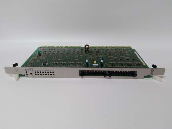
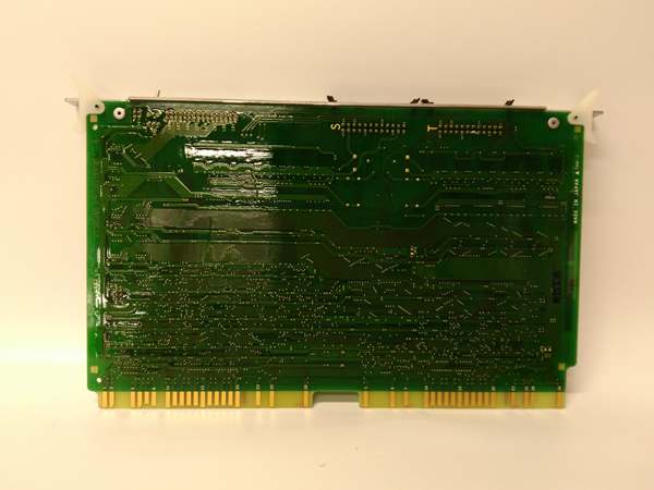
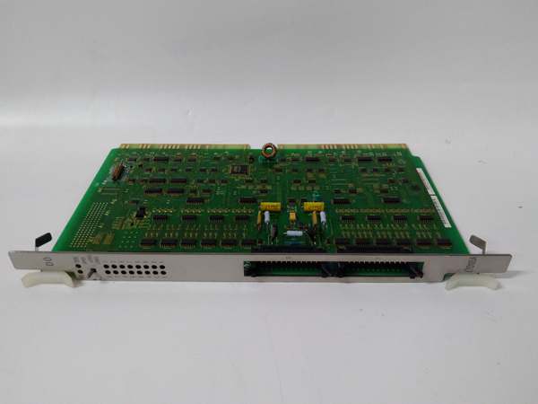
HITACHI LYD105A
The Real-World Problem It Solves
Your PLC makes decisions in logic, but you need muscle to move the real world—motors start, valves shift, solenoids fire, lights signal status. Solid-state outputs die fast switching inductive loads or handling high currents. The LYD105A uses mechanical relays to switch moderate power loads directly from the PLC, with isolation protecting the controller from field transients and ground faults. It’s the bridge between your logic and your actuators.
Where you’ll typically find it:
- Control panels driving 24VDC solenoid valves and pilot lights
- Conveyor systems controlling motor starters and warning indicators
- Packaging machinery triggering pneumatic cylinders and status beacons
Bottom line: This module gives your PLC the switching capability to control low-to-medium power field devices without intermediate contactors.
Hardware Architecture & Under-the-Hood Logic
The LYD105A is a slave output module hanging on the Hitachi backplane. No onboard processor doing complex math—it’s a driver circuit with relay switches that the CPU commands via the internal bus.
-
Backplane Communication: The CPU sends output state commands to the LYD105A over the H-Series internal bus during its I/O scan cycle. The module receives a data word representing the desired ON/OFF state for each of the 8 channels.
-
Optical Isolation: Each channel’s command signal passes through an optocoupler before hitting the relay driver. This isolates the PLC backplane from field-side voltage spikes, ground loops, and wiring faults.
-
Relay Driver Circuit: The isolated logic signal drives a transistor that energizes the relay coil. Current limiting and protection diodes prevent flyback damage from inductive kickback when the relay de-energizes.
-
Mechanical Relay Switching: Each channel uses an electromechanical relay with contacts (typically SPDT Form C). When energized, the common contact flips to the normally-open (NO) terminal, completing the circuit to your field device.
-
Output Status Feedback: The front panel LED for each channel reflects the actual relay contact state, not just the command signal. If a relay welds or fails, the LED shows the true field condition.
-
Fault Detection: The module monitors for open circuits (broken field wiring) and short circuits (field device failure). Diagnostic bits get packed into the return data word to the CPU for alarm handling.
-
Flyback Protection: Inductive loads like solenoids generate voltage spikes when switched off. The module includes suppression diodes or RC networks across each relay contact to clamp these transients and protect the relay contacts from arcing.
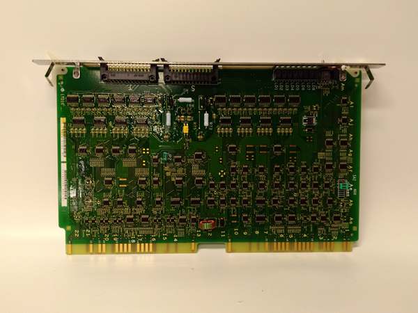
HITACHI LYD105A
Field Service Pitfalls: What Rookies Get Wrong
Inductive Load Suppression Missing
I’ve seen techs wire a 24VDC solenoid directly to the LYD105A with no flyback protection. Every time the relay opens, the inductive kick spikes the contacts. After a few thousand cycles, the relay welds shut—your solenoid won’t turn off and production keeps running.
- Field Rule: Install a diode (1N4007 or equivalent) across inductive loads, cathode to positive. For AC loads or when you can’t add diodes, use an RC snubber network across the relay contacts. Protect the relay, or you’ll be swapping modules every six months.
Overloading 0.5A Contact Rating
New engineers assume 0.5A is headroom and try switching 1A motor starters or two parallel solenoids on one channel. Contacts overheat, weld, or the module’s overcurrent protection trips unpredictably.
- Quick Fix: Do the math. Add up the steady-state current of all devices on each channel. If you’re close to 0.4A, use an interposing relay or contactor to handle the actual load. Let the LYD105A drive the coil, not the motor.
Forgetting Contact Derating
Relays are rated differently for resistive (heaters, lights) vs. inductive (motors, solenoids) loads. That 0.5A rating is for resistive. Switching a 24VDC solenoid at 0.4A will burn contacts faster than a 0.4A indicator light.
- Field Rule: Derate relay current by 50% for inductive loads. If your solenoid draws 0.3A, treat it as 0.45A and leave margin. Don’t max out the contacts—heat kills relays.
Ignoring Relay Life Expectancy
Relays aren’t forever. Even at rated load, you get maybe 100,000 operations. High-cycle applications (fast packaging machines at 10Hz) will burn through a LYD105A in days, not years.
- Field Rule: Count your cycles. If a channel switches more than a few times per hour, consider a solid-state output module or external interposing relays. The LYD105A is for slow switching—valves, pumps, status lights, not high-frequency PWM.
Mixing AC and DC on Same Module
Techs try to switch 120VAC contactors and 24VDC solenoids from the same LYD105A. Some relay variants are DC-only. Mix it up and you’ll smoke the module or get erratic switching.
- Quick Fix: Check the module datasheet for your specific hardware revision. If it’s rated for 24VDC only, keep AC loads on a different output type. Don’t guess—verify the relay contact voltage rating before wiring.
Leaving Unused Channels Floating
Channels not connected to field devices get left open. Dust and humidity cause leakage paths across terminals. Unpowered channels can ghost-activate from crosstalk or induce false readings in monitoring circuits.
- Field Rule: Tie unused output commons to a clean ground or install dummy loads (resistors) on floating outputs. Keep the circuit terminated, even when you’re not using it.
Please note: The listed price is for reference only and is not binding. Final pricing and terms are subject to negotiation based on current market conditions and availability.


