
Description
Hard-Numbers: Technical Specifications
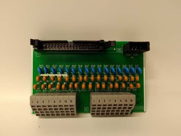
- Module Type: Digital Input (DI) Module
- Input Channels: 8 or 16 digital inputs (configuration varies by specific revision)
- Input Voltage: 24 VDC nominal
- Input Current: 4.4 mA (24V type) / 2.4 mA (12V type) per channel
- Logic Level: TTL-compatible sinking/sourcing configuration
- Response Time: Typical <10ms input-to-CPU scan
- Isolation: Optical isolation per channel (typical 500-1500V rating for DI modules)
- Operating Temperature: 0°C to +70°C (ambient)
- Storage Temperature: -25°C to +85°C
- Derating: 2.5%/K above +60°C (if applicable)
- Power Consumption: Module backplane draw varies (typically <200mA from PLC rack)
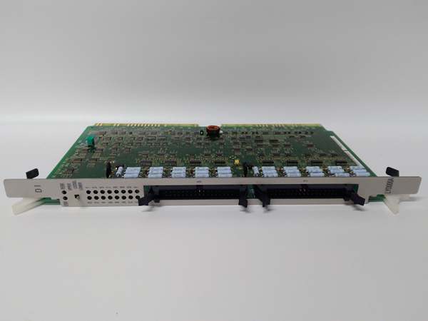
- Dimensions: 16.0 cm × 12.0 cm × 4.1 cm
- Weight: 0.36 kg
- Mounting: Plug-in to Hitachi H-Series rack
- Wiring: Screw terminal or connector-based (depends on specific terminal block variant)
- LED Indicators: Individual channel status LEDs + module power/fault LED
- Diagnostic: Input fault detection (open circuit/short circuit)
The Real-World Problem It Solves
Field devices push buttons, limit switches, photoeyes, and proximity sensors generate on/off signals that your PLC needs to see. Without a reliable DI module, you’re flying blind—critical process interlocks could fail silently, safety gates might not register as closed, and production lines 终止 for unknown reasons. The LYD000A converts those 24VDC field signals into logic levels the Hitachi CPU can process, with isolation protecting the controller from surges and ground loops.
Where you’ll typically find it:
- Manufacturing assembly lines monitoring push buttons and limit switches
- Material handling systems tracking proximity sensors and photoeyes
- Safety interlock systems monitoring emergency 终止s and guard switches
Bottom line: This module is your eyes on the factory floor—converting field device states into data the controller can act on.
Hardware Architecture & Under-the-Hood Logic
The LYD000A is a slave I/O module that hangs on the Hitachi PLC backplane. No onboard processor does complex logic—it’s a signal conditioning and isolation interface that talks to the CPU via the internal bus.
-
Field Signal Conditioning: Each input channel receives 24VDC from the field device. An RC filter network debounces the signal to eliminate chatter from mechanical contacts or noisy environments.
-
Optical Isolation: The conditioned signal passes through an optocoupler per channel. This isolates field-side wiring from the PLC backplane, protecting the CPU from voltage spikes, ground loops, and wiring faults.
-
A/D Conversion & Latching: The isolated analog signal gets converted to a digital logic state (0 or 1). The module latches this state until the next CPU scan cycle reads it via the backplane bus.
-
Backplane Communication: The CPU polls the module over the internal H-Series bus during its I/O scan. The module responds with the current status of all channels as a packed data word.
-
Status Indication: Each channel drives an LED on the front panel—green for ON, off for OFF. The module monitors for open circuits or short circuits and can flag faults to the CPU.
-
Diagnostic Reporting: If a channel detects a fault (e.g., input stuck ON or OFF), the module sets a diagnostic bit in the data word. The CPU can read this bit and trigger an alarm or fault routine.
HITACHI LYD000A
Field Service Pitfalls: What Rookies Get Wrong
Mixing Sinking and Sourcing Inputs
New engineers assume all 24VDC inputs are wired the same. The LYD000A needs to know whether your field devices are PNP (sourcing) or NPN (sinking). Wire it wrong, and the LED stays off no matter what the switch does.
- Field Rule: Check your field device specs. PNP devices output +24V when ON—connect to sinking input modules. NPN devices pull to ground when ON—use sourcing inputs. Don’t guess.
Ignoring Input Voltage Range
I’ve seen 120VAC accidentally wired to a 24VDC input. Smoke escapes, the module is dead, and you’re scrambling for a spare. Even 24VAC can damage DC inputs over time.
- Quick Fix: Verify field voltage before applying power. Use a multimeter on the field wiring. If it’s AC or >30VDC, 终止 and find the right module or add an interposing relay.
Missing Ground Common Return
Techs run a single wire to the input terminal and call it done. Without a common return (0VDC) reference from the field device back to the module, the circuit isn’t complete and the input never triggers.
- Field Rule: Every input needs two wires—signal (+24V) and return (0VDC). Ensure your field device’s negative terminal is tied to the module’s COM terminal or the PLC’s common bus.
Daisy-Chaining COM Terminals
To save wire, guys daisy-chain 16 inputs through a single COM terminal screw. One loose connection or corroded wire takes down the whole bank of inputs.
- Field Rule: Keep COM runs short. If you’re sharing a common across many inputs, use a terminal block with proper current capacity and secure each wire individually.
Forgetting Input Debounce Time
Mechanical switches chatter on closure—multiple ON/OFF transitions in milliseconds. The PLC might count 20 pulses for one button press if debounce isn’t set right.
- Quick Fix: Configure input filter time in the Hitachi programming software. For push buttons and limit switches, 10-20ms debounce is typical. For high-speed counters, you might need faster response.
Hot-Swapping Without Power Down
Hitachi H-Series racks aren’t always hot-swappable. Pulling a LYD000A live can backfeed voltage into the backplane, crashing the CPU or damaging other modules.
- Field Rule: Power down the entire rack before inserting or removing I/O modules. Unless the documentation explicitly says hot-swap is supported, assume it’s not.
Please note: The listed price is for reference only and is not binding. Final pricing and terms are subject to negotiation based on current market conditions and availability.


