
Description
Hard Numbers: Technical Specifications
- Processor: 8-bit Freescale 68HC11 MPU (2 MHz clock speed)
- Memory: 24 KB EPROM, 32 KB Static RAM, 512 Bytes EEPROM
- Digital Inputs: 16 discrete inputs (12-130 V DC range)
- Control Outputs: 8 Relay Outputs (Form C contacts, 3A max rating)
- Analog I/O (Optional): 16 Inputs OR 8 Inputs / 8 Outputs (via plug-in daughter boards)
- Analog Resolution: 14-bit (Inputs), 12-bit (Outputs)
- Isolation Rating: 1500 V AC (I/O to Backplane/Logic)
- Communication Ports: 2x D.20 Link Ports (Daisy-chain), 1x RS-232 Maintenance Port
- Power Draw: 20-60 V DC Input, 5W Typical / 11W Full Load
- Operating Temperature: -40°C to +70°C
WESDAC D20C
The Real-World Problem It Solves
Centralized control systems get bogged down processing thousands of individual status points and maintaining watchdog timers on relays. The WESDAC acts as a smart front-end, offloading the grunt work of signal conditioning, chatter filtering, and local control logic from the main D20 processor. It ensures that noisy field signals don’t crash the backbone of your RTU.
Where you’ll typically find it:
- In the backplanes of GE D20/D200 RTUs at transmission substations, monitoring breaker status and tap changers.
- Bolted into turbine control panels at power plants, handling local trip/close logic for generators.
- Inside water treatment pump houses, managing local motor starter interlocks and level switch feedback.
It bridges the gap between ancient electromechanical relays and modern SCADA without requiring a complete rack replacement.
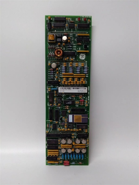
Hardware Architecture & Under-the-Hood Logic
This isn’t just a passive terminal block; it’s a semi-autonomous processing node. The onboard 68HC11 microprocessor handles the heavy lifting for its specific slice of I/O, communicating back to the main CPU via the proprietary D.20 Link protocol.
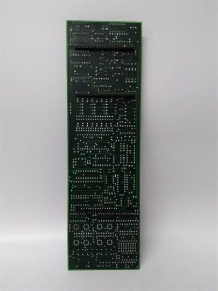
- Signal Termination: Field wires land on the detachable WESTERM termination board, which provides surge suppression (MOVs) and initial noise filtering before the signal hits the logic.
- Local Processing: The 68HC11 scans the digital inputs, applies software-based chatter filtering, and updates its local memory map. For analog channels, it handles the A/D or D/A conversion locally.
- Control Security: The processor continuously runs control output security algorithms. If it loses communication with the master processor or detects a watchdog timeout, it can independently drive the relays to a safe, pre-programmed state.
- Backplane Communication: The module packages its I/O data and shoots it across the D.20 Link to the main D20 processor, keeping the backplane traffic light and deterministic.
WESDAC D20C
Field Service Pitfalls: What Rookies Get Wrong
Overlooking the Local/Remote Switch
Rookies will spend hours troubleshooting why a won’t talk to the master processor, checking cables and software, completely ignoring the physical Local/Remote switch on the faceplate. If it’s in ‘Local’, the communications links are shut down, and the module is effectively offline.
- Field Rule: Always check the physical switches first. Cycle the L/R switch to ‘Remote’ and verify the status LED changes. If the module remains offline, check the DIP switch addressing against the system configuration print.
Improper Removal of the Termination Board
When swapping a faulty , rookies often try to pull the processing board and the termination board off the rack simultaneously. This stresses the fragile ribbon connector between them and can bend the backplane pins.
- Quick Fix: The module is a two-piece assembly for a reason. Unplug the D.20 Link cable, unscrew the retaining screws, and gently separate the WESDAC processing board from the WESTERM termination board beforeremoving it from the rack. Leave the termination board mounted to preserve your field wiring.
Ignoring Surge Suppression Failures
The has robust Metal Oxide Varistors (MOVs) on the input channels to protect against field transients. Rookies assume if the LED is lit, the input is good. They don’t realize a nearby lightning strike or large motor startup can cook the MOV, leaving the input circuit permanently latched or dead.
- Field Rule: If a digital input reads incorrectly and the field device checks out, pull the module and visually inspect the termination resistors and MOVs. Use a multimeter to check the input impedance; a dead MOV will usually show a short to ground.
Commercial Availability & Pricing Note
Please note: The listed price is for reference only and is not binding. Final pricing and terms are subject to negotiation based on current market conditions and availability.


