
Description
Hard Numbers: Technical Specifications
- Output Channels: 8 Independently Configurable Channels
- Resolution: 12-Bit (for standard models), 14-Bit (for high-precision variants)
- Output Ranges: 0-10V DC, ±10V DC, 4-20mA, 0-20mA (Jumper Selectable)
- Accuracy: ±0.1% of Full Scale Range (FSR) at 25°C
- Isolation Rating: 1500V AC Optically Isolated (Outputs to Backplane)
- Power Draw: +5V DC @ 200mA (Typical), +24V DC @ 50mA (Typical)
- Operating Temperature: -40°C to +70°C (-40°F to +158°F)
- Protocol Support: D20 Backplane Protocol (Memory-mapped I/O)
WESDAC D20C
The Real-World Problem It Solves
Modern control systems speak in zeros and ones, but the field still runs on analog. Your D20 RTU crunches the numbers to adjust a steam turbine governor or a chemical plant control valve, but it needs a bridge to translate those digital commands into real-world physical signals (like a 4-20mA current loop). The WESDAC acts as that critical translator, taking the digital output from the CPU and turning it into a precise, isolated analog signal that heavy machinery can actually use.
Where you’ll typically find it:
- In D20/D200 RTUs at power plants, driving analog control loops for generators and turbines.
- Mounted in industrial control cabinets, interfacing a GE PLC with legacy analog field devices.
- Inside water treatment facilities, controlling the opening and closing of large flow-control valves.
It eliminates the need for external signal isolators and messy wiring blocks by integrating high-precision conversion and optical isolation directly onto a single, replaceable board.
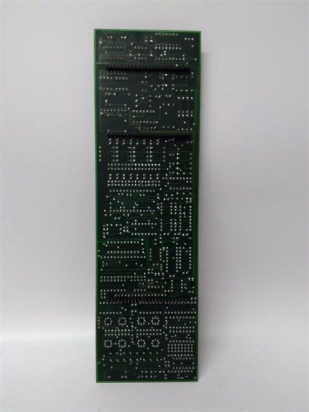
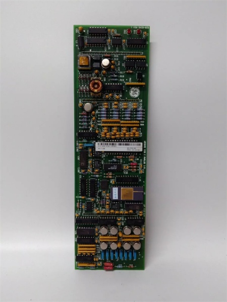
Hardware Architecture & Under-the-Hood Logic
This module doesn’t have its own processor; it’s a slave device sitting on the D20 backplane. When the main CPU needs to send an analog value to the field, it writes a digital word to the WESDAC ‘s designated memory address.
- Data Latch: The module continuously monitors the backplane for data updates. Once a new digital value is detected, it latches the data to prevent glitches during transmission.
- Digital-to-Analog Conversion: The latched digital code is fed into a precision D/A converter chip, which generates a corresponding analog voltage.
- Signal Conditioning & Amplification: The raw analog voltage is then conditioned, amplified, and converted into the user-selected output range (e.g., 4-20mA) with the help of onboard op-amps and current sources.
- Optical Isolation: Before leaving the module, the analog signal passes through optically isolated amplifiers. This ensures that any electrical noise, surges, or ground loops from the field wiring cannot feed back into and damage the sensitive digital logic of the D20 backplane.
WESDAC D20C
Field Service Pitfalls: What Rookies Get Wrong
Incorrect Jumper Configuration (Current vs. Voltage Mode)
Rookies often assume the module is plug-and-play. They leave the factory-default jumpers in place (usually voltage mode) and wonder why their 4-20mA control valve isn’t responding correctly, or worse, they burn out the module’s output drivers by connecting a low-impedance loop to a voltage-configured output.
- Field Rule: Always trace the jumpers (JP1-JP8) on the board to match your field wiring. If you’re driving a 4-20mA loop, ensure the jumpers are set for current output. If the output is dead, check the jumper first, then check the software scaling.
Ignoring DIP Switch Addressing Conflicts
The uses DIP switches (SW1) to set its base address on the backplane. A rookie might install a spare card, forget to check the DIP switches, and accidentally set the same address as another module (like a WESPIO or another WESDAC). This causes a backplane addressing conflict, leading to erratic behavior or a system fault.
- Quick Fix: Before powering up a replacement, compare the DIP switch positions on the new card with the faulty one you pulled out. Better yet, document the switch settings of every module in your rack in a logbook. Consistency prevents headaches.
Testing Outputs with a Standard Multimeter in Current Mode
When testing a 4-20mA output, rookies often try to measure the current directly by putting their multimeter in series with the field device. This breaks the loop and can cause the ‘s output to rail or fluctuate, leading the tech to believe the card is bad.
- Field Rule: Measure the voltage drop across a precision 250Ω or 500Ω resistor placed in parallel with the output. Ohms law (V = I x R) gives you the current without breaking the loop. If you must break the loop to measure current, use a bypass jumper wire to keep the loop closed while you probe.
Commercial Availability & Pricing Note
Please note: The listed price is for reference only and is not binding. Final pricing and terms are subject to negotiation based on current market conditions and availability.


