
Description
Hard Numbers: Technical Specifications
- Bus Interface: VMEbus (A16/D16, A24/D16)
- Output Channels: 16 single-ended analog outputs
- Resolution: 12 bits (4096 steps)
- Voltage Output Range: +5V, +10V, ±5V, ±10V (Software Selectable)
- Current Output Range: 4-20mA, 0-20mA (Loop Powered)
- Settling Time: 10 µs to 0.012% of full scale
- Isolation Rating: 1500V DC (Output-to-Backplane)
- Operating Temperature: 0°C to +55°C
- Power Consumption: +5V @ 1.5A, ±12V @ 0.4A typical
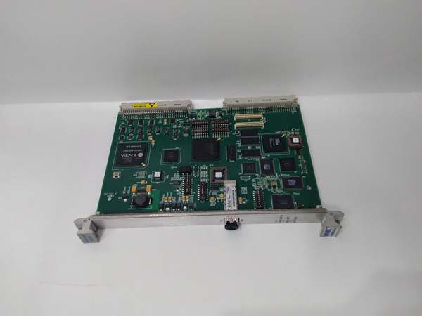
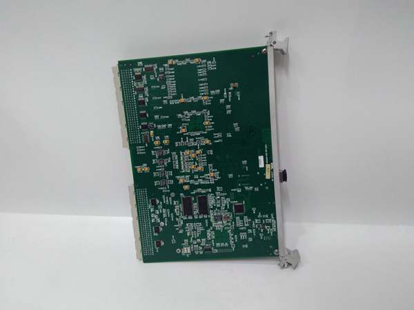
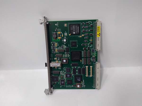
GE VMIVME-5565-010000
The Real-World Problem It Solves
Updating analog outputs via slow software loops causes jitter in control valves. This leads to oscillations in turbine fuel splits or generator excitation. This board provides deterministic, hardware-level analog output updates directly from the VMEbus.
Where you’ll typically find it:
- In gas turbine control crates, driving fuel metering valves and inlet guide vanes.
- Inside paper mill drive systems, controlling sectional draw on the paper machine.
- Within power plant boiler controls, positioning damper actuators.
It delivers stable, glitch-free analog signals even during VMEbus data bursts.
Hardware Architecture & Under-the-Hood Logic
This is a dedicated digital-to-analog converter (DAC) array. It has no processor; it relies on VMEbus writes to update the output latches. The onboard circuitry handles the heavy lifting of maintaining stable output voltages/currents.
- Data Latching: The VMEbus master writes a 12-bit word to the module’s base address. This data is latched into the output register.
- DAC Conversion: The latched digital value is fed into a precision 12-bit DAC. The DAC converts the digital word into a proportional analog voltage.
- Output Buffering: The analog voltage is buffered through a unity-gain amplifier. For current mode, the voltage is converted to a 4-20mA loop current via an onboard transconductance amplifier.
Field Service Pitfalls: What Rookies Get Wrong
Misconfiguring Output Mode (Voltage vs. Current)
A rookie sets the software for 4-20mA but leaves the physical jumpers set for voltage output. The valve doesn’t move, and they start swapping I/O cards.
- Field Rule: Verify the onboard configuration jumpers (W1-W16) match the software setup. If the jumper is set to voltage and the software commands current, you’ll see 0V at the terminal.
Shared Ground Loops on Single-Ended Outputs
Techs tie the negative terminals of multiple outputs together, creating ground loops. This causes crosstalk and inaccurate readings on adjacent channels.
- Quick Fix: Treat each output as a floating pair. If you must common the grounds, do it at one point only—preferably at the receiving instrument. Use twisted pair wiring for all analog runs.
Ignoring External Loop Power for Current Mode
They try to drive a 4-20mA valve without providing external 24V loop power to the . The output stays dead.
- Field Rule: For current mode (4-20mA), you must supply external power to the module’s loop power terminals. The board itself does not generate the loop supply; it only sinks the current.
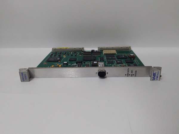
GE VMIVME-5565-010000
Commercial Availability & Pricing Note
Please note: The listed price is for reference only and is not binding. Final pricing and terms are subject to negotiation based on current market conditions and availability.


