
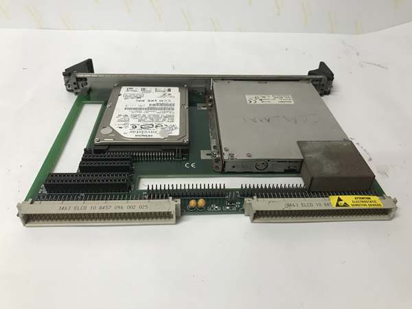
Description
Hard Numbers: Technical Specifications
- Bus Interface: VMEbus (A16/D16)
- Input Channels: 16 differential analog inputs
- Resolution: 12 bits
- Input Ranges: ±5V, ±10V, 0-10V, 0-5V (Software Selectable)
- Conversion Time: 10 µs per channel
- Throughput Rate: 100 kHz maximum
- Isolation Rating: 500V DC (Channel-to-Backplane)
- Operating Temperature: 0°C to +55°C
- Power Consumption: +5V @ 1.2A, ±12V @ 0.3A typical
- Dimensions: 6U VME (Single Width)
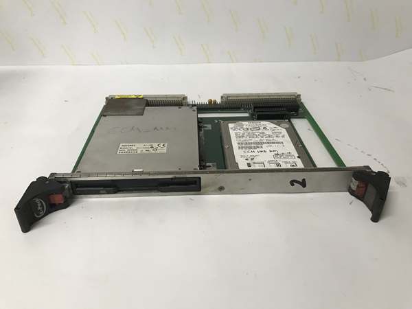
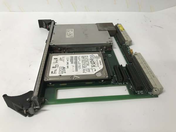
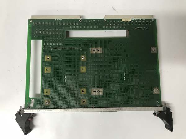
GE VMIVME-7452
The Real-World Problem It Solves
Scanning 16 analog channels through slow serial links introduces unacceptable jitter in turbine control loops. This board slams data directly onto the VMEbus at hardware speed. It eliminates software polling delays and ensures deterministic data acquisition for critical control algorithms.
Where you’ll typically find it:
- Inside GE Speedtronic Mark VI turbine control crates, monitoring vibration and temperature sensors.
- In nuclear power plant protection systems, acquiring safety-critical analog signals.
- Within steel mill process control, handling high-noise thermocouple and 4-20mA inputs.
It provides deterministic, high-density analog data without burdening the main CPU.
Hardware Architecture & Under-the-Hood Logic
This is a hardwired data acquisition engine. It doesn’t run code; it uses dedicated ADC chips and FIFO buffers. The module sits on the VMEbus as a slave device, waiting for the master CPU to request data.
- Analog Multiplexing: The 16 differential inputs are routed through a high-speed analog multiplexer to a single 12-bit successive approximation ADC.
- Sample-and-Hold: Each channel passes through a sample-and-hold circuit to ensure stable voltage during conversion.
- Data Buffering: Converted digital values are stored in a FIFO buffer, ready for the VMEbus master to read via programmed I/O or DMA.
Field Service Pitfalls: What Rookies Get Wrong
Incorrect Input Range Selection
Rookies set the software range to ±10V but wire a 4-20mA transmitter expecting 0-5V. The ADC clips the signal, giving garbage readings.
- Field Rule: Verify the physical input signal voltage matches the software-configured range. Use a voltmeter on the input terminals before blaming the board.
Ground Loop Induced Noise
Techs connect shield drains to both the sensor ground and the VME chassis ground. This creates a ground loop, injecting 60Hz noise into the differential inputs.
- Quick Fix: Ground the shield at one end only—preferably at the sensor end. Ensure the VME crate has a solid single-point earth ground.
Overlooking VMEbus Addressing
Installing the board with incorrect rotary switch settings causes address conflicts. The CPU can’t see the board, and rookies assume it’s dead.
- Field Rule: Set the base address switches (SW1) to match the configuration file. If the address overlaps with another module, the bus will lock up.
GE VMIVME-7452
Commercial Availability & Pricing Note
Please note: The listed price is for reference only and is not binding. Final pricing and terms are subject to negotiation based on current market conditions and availability.


