
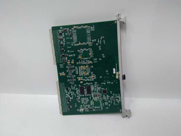
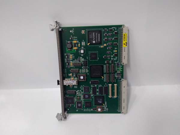
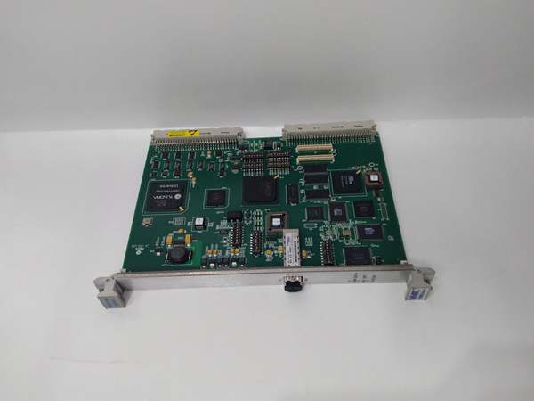
Description
Hard Numbers: Technical Specifications
- Bus Interface: VMEbus (Master/Slave, A16/A24/A32)
- Memory Capacity: 128 MB SDRAM (Error Correcting)
- Data Transfer Rate: Up to 160 MB/s (VME PIO), 2.125 Gbaud (Fiber)
- Fiber Connectors: Two LC-style multi-mode (Tx/Rx)
- Max Nodes: 256 nodes per fiber network
- Interrupts: VMEbus Interrupts (Levels 1-7)
- DMA Channels: Dual DMA Engines
- Form Factor: 6U VME (Single Width)
- Operating Temp: 0°C to +55°C (Commercial)
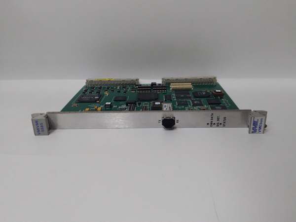
GE VMIVME-5565-010000
The Real-World Problem It Solves
Standard Ethernet and TCP/IP stacks introduce unpredictable latency and jitter. In turbine controls or flight simulators, waiting for a software handshake means lost data and missed control cycles. This board creates a shared memory pool where data written to one node appears instantly at all others, bypassing the CPU and OS entirely.
Where you’ll typically find it:
- Inside GE Speedtronic Mark VIe/VME turbine control crates for inter-processor communication.
- In full-motion flight simulators, linking host computers to I/O racks.
- Within high-energy physics labs, synchronizing data acquisition across hundreds of channels.
It provides hardware-level determinism that software protocols can’t touch.
Hardware Architecture & Under-the-Hood Logic
This is a hardware-level memory replicator. It doesn’t run an OS; it’s a gatekeeper for the VMEbus backplane. The onboard FPGA manages the fiber link and SDRAM, mapping network data directly into the VME address space.
- Bus Mastering: The module arbitrates for VMEbus control to read/write data directly to/from the backplane memory.
- Memory Mirroring: Data written to the local 128MB SDRAM is immediately serialized and broadcast over the 2.125 GHz fiber link to all other nodes.
- Interrupt Passing: A write operation on Node A can trigger a hardware interrupt on Node B, signaling fresh data without constant polling.
GE VMIVME-5565-010000
Field Service Pitfalls: What Rookies Get Wrong
Fiber Polarity Mix-Up
Rookies treat LC connectors like standard Ethernet and cross-connect Tx to Tx. The link stays dark, and they blame the board.
- Field Rule: Follow the golden rule: Transmit (Tx) on this board must go to Receive (Rx) on the next. Use a visual fault locator (VFL) if the link LEDs don’t light.
VMEbus Address Collisions
Installing the board with a default address that conflicts with another card on the backplane. The crate locks up, and the rookie starts swapping good boards.
- Quick Fix: Check the rotary hex switches (SW1/SW2) on the front panel. Ensure the base address matches the VMEbus configuration file. If two cards share the same address, the bus will fault.
Ignoring Termination Resistors
In a chain of reflective memory nodes, forgetting to terminate the last node in the ring. Signal reflections cause data corruption.
- Field Rule: Ensure the last board in the fiber loop has its termination enabled via the onboard jumper or software setting. Every node in between must have termination disabled.
Commercial Availability & Pricing Note
Please note: The listed price is for reference only and is not binding. Final pricing and terms are subject to negotiation based on current market conditions and availability.


