
Description
Hard Numbers: Technical Specifications
- Bus Interface: VMEbus (Master/Slave capability)
- Memory Capacity: 128 MB SDRAM (64 MB usable for some configurations)
- Data Transfer Rate: 2.125 Gbaud (Fiber), up to 160 MB/s (VMEbus PIO)
- Fiber Connectors: Two LC-style multi-mode connectors (Tx/Rx)
- Maximum Nodes: Supports up to 256 nodes in a single reflective memory network
- Interrupts: Supports VMEbus interrupts (Levels 1-7)
- DMA Engine: Dual DMA channels for background block transfers
- Dimensions: Single-width, 6U VME form factor
- Operating Temperature: 0°C to +55°C (Commercial grade)
GE VMIVME-5565-010000
The Real-World Problem It Solves
Trying to synchronize high-speed I/O across multiple chassis using standard Ethernet introduces unpredictable latency and jitter. That’s a fatal flaw in systems like flight simulators or multi-axis motion control. This board creates a shared, deterministic memory pool across distant hosts, ensuring every node sees data updates simultaneously without software overhead.
Where you’ll typically find it:
- In full-flight simulator motion bases, linking host computers to analog and discrete I/O stations.
- Inside large telescope arrays, coordinating the precise movement of segmented mirrors.
- Within power generation gas turbine controls, bridging real-time data between safety and control processors.
It bypasses the TCP/IP stack entirely, dumping data directly into the VMEbus memory map at hardware speeds.
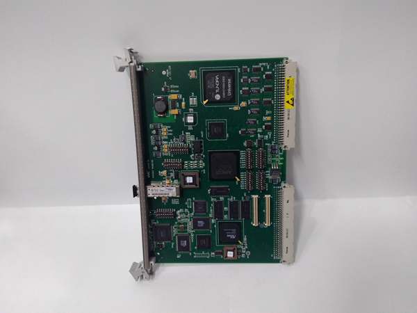
Hardware Architecture & Under-the-Hood Logic
This board acts as a hardware-level memory replicator on the VMEbus. It doesn’t run an operating system; it purely handles bus mastering and DMA transfers. The onboard FPGA manages the fiber interface and SDRAM, presenting the network data directly to the VMEbus address space.
- Bus Arbitration: The module requests VMEbus mastership to access the backplane memory or I/O registers.
- Local Buffer Management: Data intended for the network is staged into the 128MB SDRAM. The dual DMA engines handle the heavy lifting of moving data between the VMEbus and the fiber transmitter.
- Optical Transmission: The FPGA serializes the memory contents and pushes them out via the 2.125 GHz LC fiber transceiver, simultaneously writing to all nodes in the loop.
GE VMIVME-5565-010000
Field Service Pitfalls: What Rookies Get Wrong
Fiber Cable Polarity
New techs treat the LC connectors like standard Ethernet SFPs and assume they auto-correct polarity. They cross-connect Tx to Tx, resulting in a dead link and a dark status LED.
- Field Rule: Always verify the fiber polarity. Pin 1 (Transmit) on board A must connect to Pin 2 (Receive) on board B. Use a fiber tester before closing the chassis.
VMEbus Address Configuration Conflicts
Rookies install the board, power up, and wonder why the master CPU throws a bus error. They overlooked the rotary hex switches or the solder jumpers setting the base address.
- Quick Fix: Verify the board’s physical address switches match the software configuration. If the addresses collide with another VME module, the backplane will lock up. Change the switches and reboot the crate.
Ignoring Bus Request Level Settings
Techs often leave the factory default bus request level, causing the board to hog the VMEbus during large DMA transfers. This starves the CPU or other critical I/O cards.
- Field Rule: Adjust the Bus Request Level rotary switch (SW2) to a lower priority if this board is choking other time-critical devices on the backplane.
Commercial Availability & Pricing Note
Please note: The listed price is for reference only and is not binding. Final pricing and terms are subject to negotiation based on current market conditions and availability.


