
Description
Key Technical Specifications
-
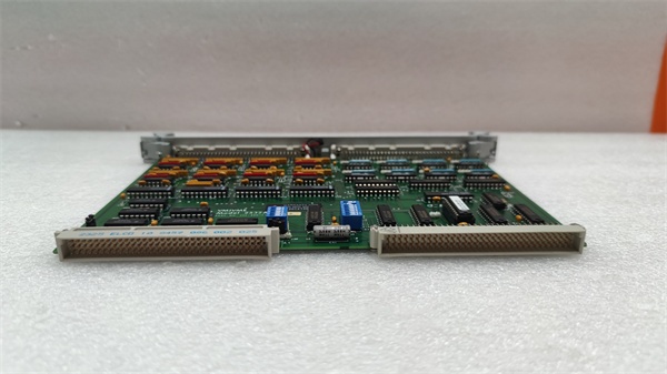
Model Number: VMIVME-4911
-
Manufacturer: GE (legacy VMIC)
-
Channels: 4 independent synchro or resolver inputs
-
Resolution: 16-bit (65 536 counts per rev)
-
Accuracy: ±0.005° typical, ±0.01° max
-
Reference: 26 V 400 Hz or 11.8 V 60 Hz jumper-select
-
Signal Range: 11.8–90 V line-to-line differential
-
Conversion Rate: 5 kHz per channel (200 µs)
-
Isolation: 500 V channel-to-bus; transformer-coupled
-
BIT: Open-reference, shorted-stator, loss-of-signal flags per channel
-
Connectors: Front-panel 96-pin DIN 41612; P2 rear I/O option
-
Power: +5 V @ 1.2 A, ±12 V @ 150 mA typical
-
Form Factor: 6U single-slot VME64 slave, A16/A24, D08/D16

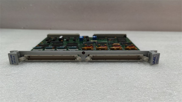
GE VMIVME-2532A
Field Application & Problem Solved
Steam-turbine throttle valves still speak synchro: a 400 Hz transmitter on the valve stem sends 26 V resolver signals back to the DCS. Old analog converters drift with temperature and give you 0.05° error—enough to hunt the governor and trip the unit on overspeed.
Steam-turbine throttle valves still speak synchro: a 400 Hz transmitter on the valve stem sends 26 V resolver signals back to the DCS. Old analog converters drift with temperature and give you 0.05° error—enough to hunt the governor and trip the unit on overspeed.
Drop in a VMIVME-4911 and you just bought precision. Each channel resolves to 0.005°, updates every 200 µs, and the BIT flag tells you if the reference winding opens or a cable shorts before the valve jerks. I’ve used this exact card on a 7FA gas-turbine inlet-guide-vane loop: four resolvers, one slot, zero calibration drift for five years.
Core value: resolver accuracy without the calibration headache. You get 16-bit position in a single read, the BIT word logs cable faults, and the front-panel FAIL LED screams before the turbine surges.
Installation & Maintenance Pitfalls (Expert Tips)
Reference frequency is jumper-hard
Board ships 400 Hz; move W1-W4 to 60 Hz if your exciter is ship-service. Forget the jumper and the converter outputs random codes that look like a runaway valve.
Board ships 400 Hz; move W1-W4 to 60 Hz if your exciter is ship-service. Forget the jumper and the converter outputs random codes that look like a runaway valve.
90 V line-to-line is max
Some old transmitters hit 115 V on open circuit. Above 90 V the input transformer saturates and accuracy falls off a cliff. Add external 5 kΩ drops or swap the transmitter—don’t try to “live with it.”
Some old transmitters hit 115 V on open circuit. Above 90 V the input transformer saturates and accuracy falls off a cliff. Add external 5 kΩ drops or swap the transmitter—don’t try to “live with it.”
BIT only flags electrical faults
Open-reference or shorted-stator sets the BIT bit, but a sticky valve stem still looks electrically perfect. For safety-critical loops, cross-check position with a second limit switch—don’t trust BIT alone.
Open-reference or shorted-stator sets the BIT bit, but a sticky valve stem still looks electrically perfect. For safety-critical loops, cross-check position with a second limit switch—don’t trust BIT alone.
Rear I/O needs shielded pairs
P2 carries the low-level resolver signals. Run individually shielded twisted pairs back to the junction box and ground the shield at the transmitter only. Otherwise 60 Hz from the exciter cable couples in and you chase 0.02° ripple that isn’t real.
P2 carries the low-level resolver signals. Run individually shielded twisted pairs back to the junction box and ground the shield at the transmitter only. Otherwise 60 Hz from the exciter cable couples in and you chase 0.02° ripple that isn’t real.
GE VMIVME-2532A
Front-panel FAIL LED is latched
FAIL LED stays on until you read the status register. If your scan task only polls position, the LED remains lit and the next fault is masked. Read the status byte every scan and clear the flags—takes one extra D08 cycle.
FAIL LED stays on until you read the status register. If your scan task only polls position, the LED remains lit and the next fault is masked. Read the status byte every scan and clear the flags—takes one extra D08 cycle.
Technical Deep Dive & Overview
The 4911 uses solid-state Scott-T transformers to convert 3-wire resolver signals into digital angle. A 16-bit tracking converter updates every 200 µs; the loop closes internally, so no external integrator is needed. Opto-isolators give 500 V working isolation, and the BIT circuit injects a test current to verify continuity of both reference and signal windings. Because the card is purely hardware-defined, there’s no firmware to corrupt—just deterministic angle data every scan.
The 4911 uses solid-state Scott-T transformers to convert 3-wire resolver signals into digital angle. A 16-bit tracking converter updates every 200 µs; the loop closes internally, so no external integrator is needed. Opto-isolators give 500 V working isolation, and the BIT circuit injects a test current to verify continuity of both reference and signal windings. Because the card is purely hardware-defined, there’s no firmware to corrupt—just deterministic angle data every scan.


