
Description
Key Technical Specifications
-
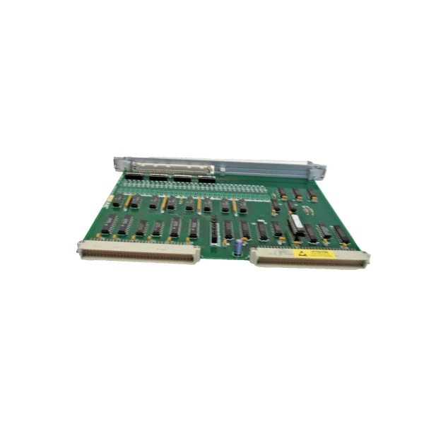
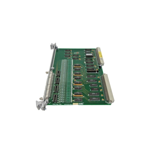
Model Number: VMIVME-4514
-
Manufacturer: GE (legacy VMIC)
-
Resolution: 12-bit ADC & DAC, monotonic over temp
-
Analog Input: 16 SE / 8 diff, ±2.5, ±5, ±10 V; 0-5, 0-10 V; 40 kHz max scan
-
Analog Output: 16 S/H channels, ±2.5, ±5, ±10 V; 0-5, 0-10 V; 10 mA source/sink
-
Conversion Time: 10 µs per channel, 15 µs with settling
-
Data Buffer: Dual-port RAM; auto-scan writes, CPU reads without handshake
-
Isolation: 500 V channel-to-bus; differential inputs 82 dB CMRR
-
Filtering: Jumper-select 36 Hz low-pass per input
-
BIT: On-board checks ADC, DAC, reference, ±12 V rails
-
Bus: VME64x slave, A16/A24, D08/D16, P2 rear I/O supported
-
Power: +5 V 1.2 A, ±12 V 100 mA typical
-
MTBF: >300 kh @ 40 °C (MIL-HDBK-217F, ground benign)

GE VMIVME-2120
Field Application & Problem Solved
Paper-machine steam-pressure loops hate latency. You have a 3-inch pneumatic valve 200 ft from the DCS rack; the operator bumps set-point 2 psi and expects the scanner to see it in <100 ms. With older single-function boards you’d dedicate one card to inputs, another to outputs, and burn two slots plus backplane time shuffling data.
Paper-machine steam-pressure loops hate latency. You have a 3-inch pneumatic valve 200 ft from the DCS rack; the operator bumps set-point 2 psi and expects the scanner to see it in <100 ms. With older single-function boards you’d dedicate one card to inputs, another to outputs, and burn two slots plus backplane time shuffling data.
VMIVME-4514 slams both sides of the loop into one slot. The auto-scan ADC samples all 16 inputs every 25 µs, drops the codes into dual-port RAM, and your PID task reads them with a single D16 burst. Meanwhile the 16 simultaneous S/H DACs update the valve and trim outputs at the same tick—no stagger, no phase lag. I’ve used this board on a governor rig in a 7FA gas-turbine package: exhaust temp sensors feed the ADC, fuel-ratio valve position comes from the DAC; loop closure is 2 ms flat and the turbine stays on-line through grid swings.
Core value: stimulus/response on one card. You save a slot, eliminate inter-card skew, and the BIT flags a drifting reference before your loop starts oscillating at 2 a.m.
Installation & Maintenance Pitfalls (Expert Tips)
P2 versus front-panel wiring—pick one
Jumpers select rear or front I/O, not both. If you land wires on the front 96-pin and leave P2 jumpers on “rear,” half your channels will float random and the loop will surge. Check silk-screen JP1-3 before you torque the screws.
Jumpers select rear or front I/O, not both. If you land wires on the front 96-pin and leave P2 jumpers on “rear,” half your channels will float random and the loop will surge. Check silk-screen JP1-3 before you torque the screws.
Auto-scan is default—turn it off for calibration
Board powers up scanning; if you hot-plug a calibrator the DAC output can bang full-scale before you blink. Use scan-disable bit in CSR, then cal, then re-enable. Saves a fried valve positioner and a lot of explaining.
Board powers up scanning; if you hot-plug a calibrator the DAC output can bang full-scale before you blink. Use scan-disable bit in CSR, then cal, then re-enable. Saves a fried valve positioner and a lot of explaining.
10 mA is it—no more
Each output is short-circuit protected, but sustained >12 mA pulls the S/H cap down and the output sags 2 %. If your electro-pneumatic converter draws 25 mA, buffer with an external 2 W op-amp; don’t expect the board to muscle it.
Each output is short-circuit protected, but sustained >12 mA pulls the S/H cap down and the output sags 2 %. If your electro-pneumatic converter draws 25 mA, buffer with an external 2 W op-amp; don’t expect the board to muscle it.
Differential inputs need both legs
Technicians love to tie the minus leg to ground “for noise.” CMRR collapses and you’ll see 60 Hz ripple equal to half your signal. Run shielded twisted pair all the way to the sensor and ground the shield at the field device only.
Technicians love to tie the minus leg to ground “for noise.” CMRR collapses and you’ll see 60 Hz ripple equal to half your signal. Run shielded twisted pair all the way to the sensor and ground the shield at the field device only.
GE VMIVME-2120
Reference drift shows up as offset first
BIT won’t flag gain error until >1 %. If your loop output hovers 0.5 % away from set-point week after week, scope the 5 V reference test point. A 50 mV drop equals 0.4 % system error—swap the reference (U27) and re-cal; takes ten minutes.
BIT won’t flag gain error until >1 %. If your loop output hovers 0.5 % away from set-point week after week, scope the 5 V reference test point. A 50 mV drop equals 0.4 % system error—swap the reference (U27) and re-cal; takes ten minutes.
Technical Deep Dive & Overview
The 4514 is basically a 12-bit backplane peripheral that behaves like two tightly coupled instruments. A 68B09-derived sequencer governs the ADC scanner, writing results to a 32-word dual-port RAM that the VME side can read at any time without handshake delay. DAC data travels the opposite direction: CPU writes to a second 32-word buffer, and on the next scan clock all 16 S/H caps update simultaneously—no stagger, no glitch.
The 4514 is basically a 12-bit backplane peripheral that behaves like two tightly coupled instruments. A 68B09-derived sequencer governs the ADC scanner, writing results to a 32-word dual-port RAM that the VME side can read at any time without handshake delay. DAC data travels the opposite direction: CPU writes to a second 32-word buffer, and on the next scan clock all 16 S/H caps update simultaneously—no stagger, no glitch.


