
Description
Hard-Numbers: Technical Specifications
-
Channels: 12 isolated analog output channels (expandable to 16 in some configurations)
-
Resolution: 12-bit D/A conversion
-
Output Ranges (Voltage): ±2.5V, ±5V, ±10V, 0-2.5V, 0-5V, 0-10V (jumper or software selectable)
-
Output Ranges (Current): 4-20mA, 0-20mA, 5-25mA
-
Accuracy: ±0.05% of full scale (voltage), ±0.08% (current loop)
-
Load Capacity: 10mA minimum (voltage mode), 20mA maximum per channel
-
Isolation: 1000Vpk channel-to-channel, channel-to-ground, channel-to-VME bus
-
Update Rate: 100 kHz
-
D/A Converter: Monolithic 12-bit converter per channel
-
Noise: <1mV rms
-
Protection: ±20V continuous overvoltage, ±50V transient protection
-
Data Coupling: Optical isolation for current loops
-
VME Interface: A24:D32 or A16:D32 slave, VMEbus Rev C compliant
-
Power Requirements: +5VDC 400mA, +12V 125mA
-
Operating Temperature: -20°C to +85°C (standard), -25°C to +85°C (extended)
-
Storage Temperature: -40°C to +125°C
-
Form Factor: 6U VME Eurocard, single-slot
-
Dimensions: 160mm × 233.35mm (6U standard)
-
Weight: 0.7 kg max

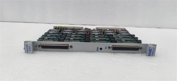
VMIVME-4150
The Real-World Problem It Solves
You know the scenario: a test stand that needs to simulate 12 different pressure transducer signals to verify a PLC’s analog input card, or a process control system where ground loops between channels are causing erratic valve positioning. The VMIVME-4150 eliminates these headaches with 12 fully isolated 12-bit outputs—each channel electrically separated from the others and from the VME bus by 1000V of optical isolation. No more ground loops, no more crosstalk between channels, and no more external signal conditioners. The software-selectable ranges let you generate ±10V for servo drives or 4-20mA for process valves from the same board.
Where you’ll typically find it:
-
Automated test equipment (ATE) racks generating precision analog stimuli for avionics or automotive ECU testing
-
Process control systems in refineries driving analog valve positioners with isolated 4-20mA loops
-
Nuclear plant simulator systems replicating reactor sensor outputs for operator training
Bottom line: It turns your VME computer into a precision analog signal generator with industrial-grade isolation, eliminating ground noise and channel-to-channel interference in multi-loop control systems.
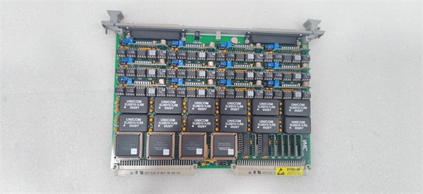
Hardware Architecture & Under-the-Hood Logic
The VMIVME-4150 is a dedicated analog output board—not a general-purpose I/O card. It sits on the VME bus as a slave device, receiving digital values from the host CPU and converting them to analog voltages or currents via 12 independent D/A converters. Each channel has its own opto-isolator, allowing channels to reference different ground potentials without creating ground loops.
Signal flow and conversion logic:
-
VME Bus Interface: The board responds to A24 or A16 addressing as a D32 slave; the host CPU writes 12-bit digital values to channel-specific registers in the board’s memory map
-
Data Latching: Double-buffered latches hold the digital value while the D/A converter settles; writing to the “update” register simultaneously updates all channels for synchronous output changes
-
D/A Conversion: Each channel’s monolithic 12-bit DAC converts the digital value to an analog voltage; reference voltages are precision-trimmed for 0.05% accuracy
-
Output Amplification: Buffer amplifiers drive the load with 10mA capability; current output modes use precision resistors to convert voltage to 4-20mA with active compliance
-
Isolation Barriers: Optical couplers separate the digital VME side from the analog output side; each channel has independent ±1000V isolation from the bus and from other channels
VMIVME-4150
Field Service Pitfalls: What Rookies Get Wrong
Confusing Voltage and Current Modes Rookies see “analog output” and assume the board automatically switches between voltage and current based on what’s connected. It doesn’t. The VMIVME-4150 requires physical jumper settings or software configuration to select voltage vs. current mode for each channel. Connecting a 4-20mA valve to a channel configured for ±10V voltage mode gives you 0-10V across a 250Ω load—barely 1.6mA, not enough to move the valve.
Field Rule: Verify the output mode configuration before connecting field devices. Voltage mode expects high-impedance loads (>10kΩ); current mode requires loop-powered devices. Check the jumper blocks or configuration registers—channels default to voltage mode from factory. A channel driving a current loop without the current-mode resistor network installed will show “open loop” faults on your smart transmitter.
Ignoring the 10mA Load Limit Each voltage output channel can source only 10mA maximum. Rookies try to drive low-impedance loads like indicator lamps or small solenoids directly. The output amplifier hits current limit, the voltage drops, and you get erratic readings that look like board failure.
Quick Fix: Calculate load impedance: R = V/I. For 10V output at 10mA, minimum load is 1kΩ. If your load is lower (e.g., 500Ω positioner), use current mode (4-20mA) instead, or add a series resistor to limit current. Never short a voltage output channel to ground—it’ll current-limit but sustained overload heats the output amp and drifts calibration.
Forgetting the 1000V Isolation is Not Infinite The 1000V isolation rating is DC working voltage, not transient surge protection. Rookies run high-voltage motor cables in the same conduit as the analog output wires, inducing transients that punch through the opto-isolators.
Field Rule: Maintain physical separation between analog output wiring and high-voltage power cables—minimum 12 inches, or use grounded metal conduit. The 1000V isolation protects against ground potential differences between channels, not against direct contact with 480VAC. If you’re driving field devices in high-voltage areas, use external signal isolators or barriers for additional protection.


