
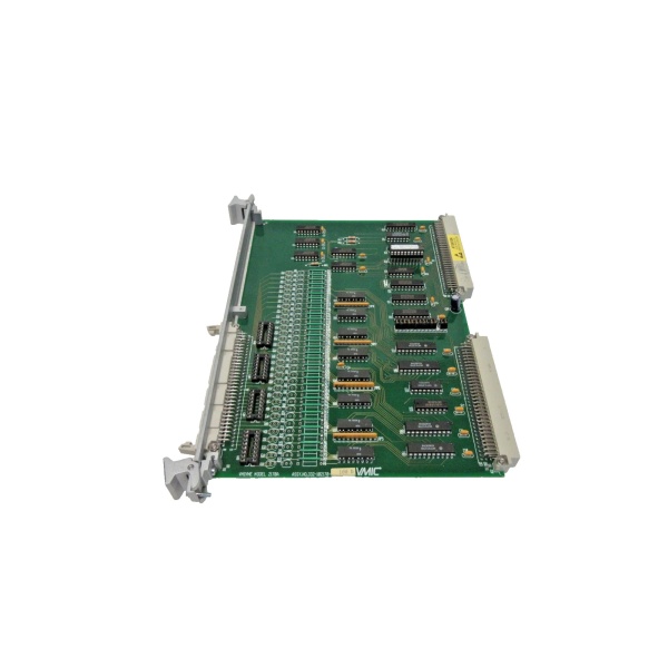
Description
Key Technical Specifications
-
Model Number: VMIVME-4100
-
Manufacturer: GE (legacy VMIC)
-
Resolution: 12-bit monotonic
-
Channels: 4, 8, 12, or 16; factory or jumper option
-
Output Range: ±10 V (-040) or 0-10 V (-140) @ 5 mA max
-
Settling Time: 8 µs max to 1 LSB
-
Accuracy: ±0.05 % FSR gain, ±0.025 % FSR offset
-
Temp-Drift: ±10 ppm/°C typical
-
Data Latch: Double-buffered per channel; simultaneous update strobe
-
Test Mode: Analog outputs routable to P2 test bus for ADC loop-back
-
Isolation: Output switches isolate field side when disabled
-
Connectors: Front-panel 64-pin DIN; rear I/O via P2
-
Power: +5 V @ 2.5 A typ., 3.6 A max
-
Form Factor: 6U single-slot VME slave, A16 short I/O map

GE VMIVME-2120
Field Application & Problem Solved
Steam-turbine inlet valves still want analog set-points: 0-10 V to the electro-hydraulic servo, ±10 V to the governor trim. Old racks solved it with four 4-channel DACs, each with its own trim-pot drift. Drop in one VMIVME-4101 and you just flattened the problem: up to 16 channels, double-buffered so you can load new values then hit a single strobe for glitch-free transfer. I’ve used this exact card on a 7FA gas-turbine inlet-guide-vane loop: 10 valves, one slot, simultaneous update, and the P2 test bus let me loop the signal back into a VMIVME-3100 ADC for closed-loop verification—no extra test cables, no calibration drift after five years.
Steam-turbine inlet valves still want analog set-points: 0-10 V to the electro-hydraulic servo, ±10 V to the governor trim. Old racks solved it with four 4-channel DACs, each with its own trim-pot drift. Drop in one VMIVME-4101 and you just flattened the problem: up to 16 channels, double-buffered so you can load new values then hit a single strobe for glitch-free transfer. I’ve used this exact card on a 7FA gas-turbine inlet-guide-vane loop: 10 valves, one slot, simultaneous update, and the P2 test bus let me loop the signal back into a VMIVME-3100 ADC for closed-loop verification—no extra test cables, no calibration drift after five years.
Core value: density plus accuracy. You get 12-bit resolution, 8 µs settling, and the BIT loop tells you if a channel drifts before the valve hunts.
Installation & Maintenance Pitfalls (Expert Tips)
Channel count is jumper-hard
Board ships 16-channel; move W1-W4 to 4, 8, or 12 if you need fewer. Forget the jumper and unused channels float random—looks like a calibration error.
Board ships 16-channel; move W1-W4 to 4, 8, or 12 if you need fewer. Forget the jumper and unused channels float random—looks like a calibration error.
Output switches isolate field side
When you disable a channel the on-card switch opens—great for maintenance—but the switch drops 0.3 V. If your servo amp wants true zero, short the switch jumper or add an external relay.
When you disable a channel the on-card switch opens—great for maintenance—but the switch drops 0.3 V. If your servo amp wants true zero, short the switch jumper or add an external relay.
P2 test bus is loop-back only
Routable to P2 for ADC verification, not for field wiring. If you land field wires on P2 you’ll inject noise straight into the test bus and corrupt every channel. Use P2 for diagnostics, front-panel for loads.
Routable to P2 for ADC verification, not for field wiring. If you land field wires on P2 you’ll inject noise straight into the test bus and corrupt every channel. Use P2 for diagnostics, front-panel for loads.
5 mA is max
Each output is buffered but limited to 5 mA. A 10 kΩ servo input is fine; a 1 kΩ load pulls 10 mA and the op-amp folds back. Check load impedance before you land wires.
Each output is buffered but limited to 5 mA. A 10 kΩ servo input is fine; a 1 kΩ load pulls 10 mA and the op-amp folds back. Check load impedance before you land wires.
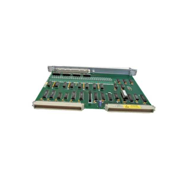
GE VMIVME-2120
Front-panel LEDs lie on over-current
LED stays green even if the channel is current-limited. If your calibration sheet shows 0.5 % low, scope the output under load—if it’s clipping at 5 mA the LED won’t tell you.
LED stays green even if the channel is current-limited. If your calibration sheet shows 0.5 % low, scope the output under load—if it’s clipping at 5 mA the LED won’t tell you.
Technical Deep Dive & Overview
The 4100 is a bank of 12-bit multiplying DACs feeding Burr-Brown 3582 output amplifiers. A 22V10 PLD decodes the short I/O address, latches data into double-buffered registers, and strobes simultaneous update via an external or internal strobe pin. Because the reference is external you can scale the full range from millivolts to ±10 V without changing gain resistors—just swap the reference zener. No firmware, no micro, just deterministic analog every scan.
The 4100 is a bank of 12-bit multiplying DACs feeding Burr-Brown 3582 output amplifiers. A 22V10 PLD decodes the short I/O address, latches data into double-buffered registers, and strobes simultaneous update via an external or internal strobe pin. Because the reference is external you can scale the full range from millivolts to ±10 V without changing gain resistors—just swap the reference zener. No firmware, no micro, just deterministic analog every scan.


