
Description
Hard-Numbers: Technical Specifications
- Channel Count: 8 independent isolated input channels
- Sensor Compatibility: 2/3/4-wire PT100/PT1000 RTD, quarter/half/full strain bridges
- Isolation Rating: 1000V DC channel-to-backplane and group-to-group galvanic isolation
- Excitation Output: Software selectable constant current or constant voltage per channel
- Filter Bandwidth: 4 Hz, 40 Hz, 400 Hz jumper-selectable low-pass filtering
- VME Bus Interface: VMEbus Rev C.1, A16/A24 addressing, D16/D32 slave operation
- Operating Temperature: 0°C to +55°C commercial industrial rating
- Power Draw: 2.8A @ 5 VDC, 14W continuous operating load
- Output Range: Scaled ±10V analog output for direct feed to VME ADC boards
- Diagnostic Hardware: Onboard BIT, open-sensor detection, and overvoltage clamping
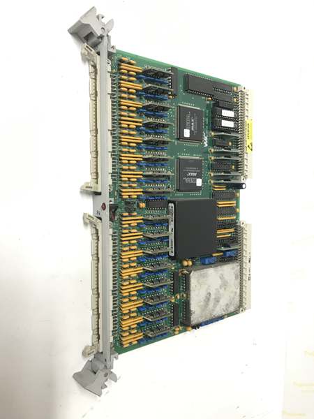
GE VMIVME-3122
The Real-World Problem It Solves
Raw RTD and strain bridge signals run in millivolt ranges, easily corrupted by VFD noise, motor contactors, and unbalanced plant grounding. Most standard analog cards lack built-in sensor excitation and isolation needed for these low-level inputs.
Where you’ll typically find it:
- GE Mark VI and Mark VIe turbine racks for bearing temperature and structural stress monitoring
- Refinery process units with high EMI environments and distributed temperature sensor runs
- Power plant balance-of-plant cabinets for boiler casing expansion, duct strain, and auxiliary equipment RTD arrays
Bottom line: It provides isolated sensor excitation, noise filtering, and signal scaling to make weak field sensor data usable by standard VME ADC hardware.
Hardware Architecture & Under-the-Hood Logic
This card functions as a dedicated VME slave front end, with isolated analog circuitry separated from digital backplane logic to block common-mode noise.
- Field RTD and bridge sensor wiring feeds into isolated input networks with transient voltage suppression.
- Onboard precision excitation circuits deliver regulated current or voltage to each sensor type.
- Instrumentation amplifiers boost low-level millivolt signals to standard 0–10V or ±10V levels.
- Configurable low-pass filters strip switching noise and 60Hz plant interference before final output.
- Conditioned analog outputs pass to downstream ADC cards; VME registers handle channel setup and fault status readback.
GE VMIVME-3122
Field Service Pitfalls: What Rookies Get Wrong
Mismatched Sensor Excitation SettingsNew technicians default to voltage excitation on RTD inputs. Incorrect excitation mode skews temperature readings and causes gradual sensor element degradation over time.
- Field Rule: Use constant current drive for all RTD devices; reserve voltage excitation solely for strain bridge circuits.
Improper Shield Termination on Low-Level WiringTechs ground cable shields at both cabinet and field junction points. Dual-grounded shields create ground loops that induce AC ripple on delicate mV signals.
- Quick Fix: Terminate shield drain wire only at the VME card end; leave field side shield floating to eliminate loop current.
Overlooking Group Isolation BoundariesRookies route high-noise and low-level sensor cables in the same bundle across isolated channel groups. Cross-talk bleeds interference into precision temperature and strain measurements.
- Field Rule: Separate wiring for each isolated 4-channel group; maintain minimum 3-inch separation from 120V control and VFD power cables.
Please note: The listed price is for reference only and is not binding. Final pricing and terms are subject to negotiation based on current market conditions and availability.


