
Description
Hard-Numbers: Technical Specifications
- Resolution: 16-bit bipolar analog-to-digital conversion
- Channel Count: 64 configurable differential or single-ended inputs
- Input Voltage Range: ±250mV to ±10V (jumper-selectable; 0–5V/0–10V unipolar)
- Max Sampling Rate: 100kHz (50kHz standard), 10μs conversion per channel
- Programmable Gain: Software-selectable ×1 or ×10 per channel
- Input Impedance: 10MΩ (differential), 5MΩ (single-ended)
- Onboard Memory: 1024-word dual-port RAM for scan data
- VME Interface: VMEbus Rev C.1, A16/A24, D08/D16/D32 slave
- Operating Temperature: 0°C to +55°C (industrial; -40°C to +85°C extended available)
- Power Draw: 3.2A @ 5VDC, 16W nominal
- Diagnostics: BIT, overvoltage protection, 4-pole low-pass filters (10Hz–10kHz)
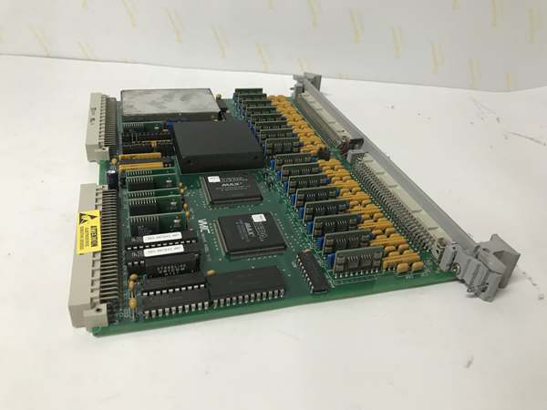
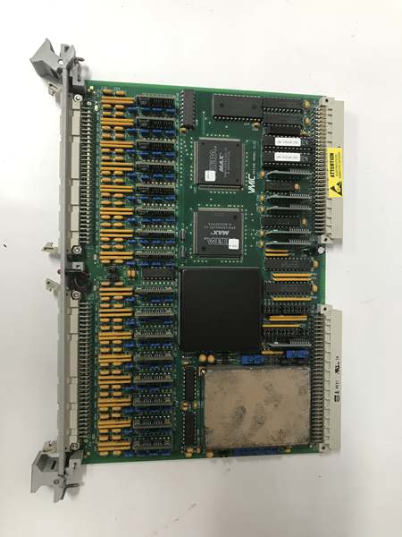
GE VMIVME-3122
The Real-World Problem It Solves
Legacy 12-bit ADCs lack the resolution for low-level sensor signals (e.g., thermocouples, strain gauges). Separate signal conditioning racks add cost and failure points.
Where you’ll typically find it:
- Mark VI/VIe turbine racks for bearing vibration, exhaust gas temperature, and lube oil pressure
- Refinery and chemical plant process units with dense, low-level analog sensor arrays
- Paper mill and steel mill data acquisition systems requiring high resolution and noise immunity
Bottom line: It integrates 16-bit precision, per-channel gain, and autoscan into one VME card, eliminating external signal conditioning and improving measurement accuracy.
Hardware Architecture & Under-the-Hood Logic
This is a self-contained high-resolution VME slave ADC with onboard scan control, reducing host CPU load.
- Analog field signals enter via a 96-pin front connector, pass through overvoltage protection and EMI filters。
- Programmable gain amplifiers (×1/×10) scale signals to optimize 16-bit ADC dynamic range。
- A dedicated scan controller cycles through 64 channels, digitizing each in 10μs and storing results in dual-port RAM。
- Autoscan runs continuously; VMEbus reads latest data directly from shared memory.
- BIT injects precision reference voltages to verify conversion accuracy without disconnecting field wiring。
GE VMIVME-3122
Field Service Pitfalls: What Rookies Get Wrong
Incorrect Gain Setting for Low-Level SignalsNew techs leave gain at ×1 for mV-range signals (thermocouples, RTDs). This wastes 90% of resolution, leading to noisy, unstable readings.
- Quick Fix: Set gain to ×10 for signals <1V; use ×1 for ±5V/±10V transmitters. Verify with BIT reference readings.
Ignoring Differential Wiring Best PracticesTechs run single-ended wiring to differential inputs. Common-mode EMI from VFDs and motor starters corrupts readings, causing drift and spikes.
- Field Rule: Use twisted shielded pair for all differential channels; ground shield at one end only; set jumpers for differential mode.
Overloading VME Backplane PowerRacks with multiple high-resolution ADCs hit 5V supply limits. Undervoltage causes intermittent scan freezes, BIT errors, and data corruption.
- Field Rule: Calculate total 5V load (3.2A per card); use dedicated VME power supplies; avoid mixing with high-current I/O cards.
Please note: The listed price is for reference only and is not binding. Final pricing and terms are subject to negotiation based on current market conditions and availability.


