
Description
Hard-Numbers: Technical Specifications
- Resolution: 12-bit bipolar analog-to-digital conversion
- Channel Count: 64 configurable differential or single-ended inputs
- Input Voltage Range: ±10mV to ±10V (jumper-selectable gain)
- Conversion Time: 15μs per channel (max 33kHz throughput)
- Input Impedance: 5MΩ (differential), 2MΩ (single-ended)
- Onboard Memory: 64-word dual-port RAM for scan data storage
- VME Interface: VMEbus Rev C.1, A16/A24, D08/D16/D32 slave
- Operating Temperature: 0°C to +55°C (standard industrial)
- Power Draw: 3.0A @ 5VDC, 15W nominal
- Diagnostics: Live/Offline BIT, overvoltage protection, 5 low-pass filter options
The Real-World Problem It Solves
Legacy systems often use multiple low-channel ADC cards, cluttering cabinets and increasing wiring complexity. Separate cards mean more points of failure and longer troubleshooting times.
Where you’ll typically find it:
- Mark VI/VIe turbine control racks for exhaust temperature, bearing vibration, and lube oil pressure monitoring
- Refinery process units with dense analog sensor arrays (pressure, level, flow transmitters)
- Power plant balance-of-plant cabinets requiring high-channel-count data acquisition
Bottom line: It consolidates 64 analog inputs onto one VME card, reducing cabinet footprint and simplifying wiring while maintaining high noise immunity.
Hardware Architecture & Under-the-Hood Logic
This is a self-contained VME slave ADC with onboard scanning logic, reducing host CPU load.
- Analog field signals enter via front-panel terminals, pass through overvoltage protection and EMI filters.
- Jumper-configured gain amplifiers scale signals to the 12-bit ADC’s optimal range.
- A dedicated scan controller cycles through channels, digitizing each in 15μs and storing results in dual-port RAM.
- Autoscan mode runs continuously on power-up; VMEbus reads latest data directly from dual-port memory.
- Built-in test circuitry injects known reference voltages to verify conversion accuracy without field signal disconnects.
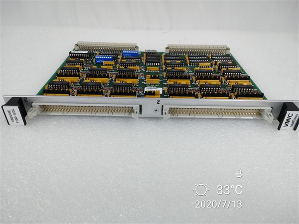
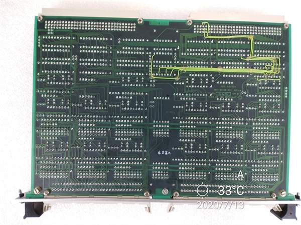
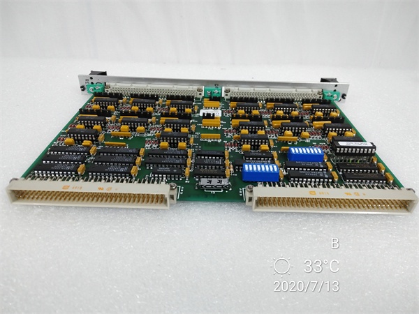
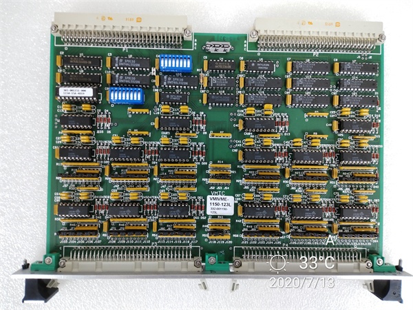
GE VMIVME-1150
Field Service Pitfalls: What Rookies Get Wrong
Mixing Differential and Single-Ended WiringNew techs often run single-ended wiring to differential channels or vice versa. This ruins common-mode noise rejection, causing unstable readings in high EMI areas (near VFDs, motor starters).
- Field Rule: Plan wiring per channel type; use twisted shielded pair for differential, single-shielded for single-ended; set jumpers accordingly.
Ignoring Gain Jumper SettingsTechs leave gain jumpers at default (×1) for low-level mV signals. This results in wasted resolution and noisy readings near zero.
- Quick Fix: Match gain to signal range (×100 for ±10mV, ×10 for ±1V, ×1 for ±10V); verify with BIT reference readings.
Overloading VME Backplane PowerRacks with multiple high-density ADC cards (like this one) often hit 5V supply limits. Undervoltage causes intermittent scan freezes and BIT errors.
- Field Rule: Calculate total 5V load (3A per card); use dedicated VME power supplies; avoid mixing with high-current I/O cards.
Please note: The listed price is for reference only and is not binding. Final pricing and terms are subject to negotiation based on current market conditions and availability.


