
Description
Key Technical Specifications
-
Model Number: VMIVME-3113A
-
Manufacturer: GE (legacy VMIC)
-
Resolution: 12-bit monotonic
-
Input Channels: 64 SE / 32 diff, ±10 mV to ±10 V jumper-select
-
Conversion Time: 15 µs per channel
-
Scan Rate: 33 kHz aggregate
-
Gain Ranges: 1, 10, 100, 200, 500× via jumper
-
Input Impedance: 5 MΩ typical
-
Data Buffer: 64-word dual-port RAM, auto-filled during scan
-
Isolation: 500 V channel-to-bus; differential CMRR 82 dB
-
Filtering: Jumper-select 36 Hz low-pass per channel
-
BIT: On-board reference & channel loop-back tests
-
Interrupts: Programmable on single sample or end-of-scan

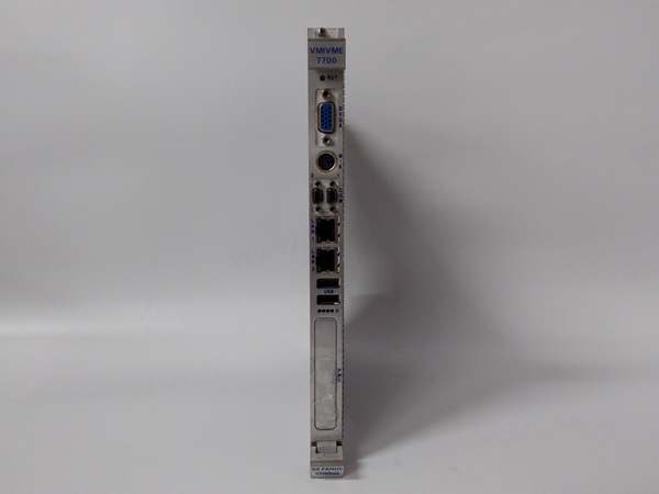
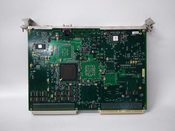
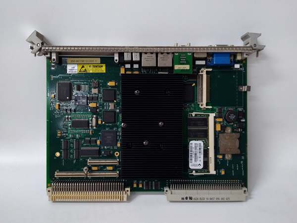
GE VMIVME-7700RC
-
Bus: VME A16/A24, D08/D16 slave
Field Application & Problem Solved
Paper-mill stock prep is a data hog: 56 RTDs across a refiner chest, six pressure transmitters on the latched blow valve, and a handful of flow meters—all feeding a single DCS node. Old-school solution used a fistful of 8-channel cards, each with its own driver and scan list. Wiring looked like spaghetti, and any time you added a sensor you re-engineered the whole rack.
Paper-mill stock prep is a data hog: 56 RTDs across a refiner chest, six pressure transmitters on the latched blow valve, and a handful of flow meters—all feeding a single DCS node. Old-school solution used a fistful of 8-channel cards, each with its own driver and scan list. Wiring looked like spaghetti, and any time you added a sensor you re-engineered the whole rack.
Plug in one VMIVME-3113A and you just flattened the problem. The board powers up in auto-scan mode—no software init—fills 64 dual-port registers at 33 kHz, and your control task simply peeks the memory address it wants. I’ve hung this exact card on a 6-foot VME crate in a 48 °C compressor building: gains set to 10× for the RTDs, 1× for the 4-20 mA drops, all on the same board. Result: one interrupt per scan, deterministic 30 µs read, and the DCS loop closes in <2 ms.
Core value: density plus plug-and-play. You get 64 channels of 12-bit data in a single slot, no scan-list programming, and the BIT pin tells you if a channel drifts before it trips the loop. That means fewer cards, fewer cables, and no 2 a.m. surprises because a calibration sheet got fat-fingered.
Installation & Maintenance Pitfalls (Expert Tips)
Auto-scan is live on power-up
The board starts scanning the instant +5 V is stable. If your field junction box isn’t landed yet, you’ll read floating inputs that look like sensor failures. Pull the scan-enable jumper until commissioning is done; saves bogus alarms.
The board starts scanning the instant +5 V is stable. If your field junction box isn’t landed yet, you’ll read floating inputs that look like sensor failures. Pull the scan-enable jumper until commissioning is done; saves bogus alarms.
Gain jumpers are channel-groups
Channels 0-15 share one jumper block, 16-31 the next, etc. Mixing RTDs (need 10×) and 10 V signals (need 1×) on the same group gives you either clipped data or 5 counts of resolution. Plan the panel layout so alike signals share a group.
Channels 0-15 share one jumper block, 16-31 the next, etc. Mixing RTDs (need 10×) and 10 V signals (need 1×) on the same group gives you either clipped data or 5 counts of resolution. Plan the panel layout so alike signals share a group.
Differential wiring is both legs
Techs love to ground the minus side “for shielding.” CMRR collapses and 60 Hz shows up as 2 % of full scale. Run twisted pair all the way to the sensor and ground the shield at the field device only.
Techs love to ground the minus side “for shielding.” CMRR collapses and 60 Hz shows up as 2 % of full scale. Run twisted pair all the way to the sensor and ground the shield at the field device only.
15 µs is per channel—not per scan
A full 64-channel scan takes 960 µs. If your control loop needs <500 µs update, cut the scan list to 32 channels with the jumper or read only the registers you care about; don’t wait for the BIT “end-of-scan” flag.
A full 64-channel scan takes 960 µs. If your control loop needs <500 µs update, cut the scan list to 32 channels with the jumper or read only the registers you care about; don’t wait for the BIT “end-of-scan” flag.
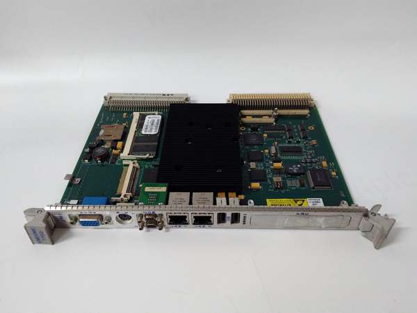
GE VMIVME-7700RC
Reference drift flags late
BIT won’t complain until the internal 4.980 V reference drifts >1 %. If your calibration sheet shows a 0.5 % offset creep over six months, scope TP9. A 50 mV drop equals 0.4 % system error—swap the reference zener (D3) and re-cal; takes ten minutes and a 5-cent part.
BIT won’t complain until the internal 4.980 V reference drifts >1 %. If your calibration sheet shows a 0.5 % offset creep over six months, scope TP9. A 50 mV drop equals 0.4 % system error—swap the reference zener (D3) and re-cal; takes ten minutes and a 5-cent part.
Technical Deep Dive & Overview
The 3113A is a scanning ADC engine glued to a VME slave interface. A 12-bit SAR converter with a 4-input multiplexer feeds a 64-word dual-port RAM; a state machine cycles through the selected channels at 33 kHz and stuffs codes without CPU handshaking. Programmable-gain instrumentation amps sit ahead of the mux; jumper-select gives you 1× to 500× so you can read thermocouple microvolts or ±10 V turbine signals on the same card.
The 3113A is a scanning ADC engine glued to a VME slave interface. A 12-bit SAR converter with a 4-input multiplexer feeds a 64-word dual-port RAM; a state machine cycles through the selected channels at 33 kHz and stuffs codes without CPU handshaking. Programmable-gain instrumentation amps sit ahead of the mux; jumper-select gives you 1× to 500× so you can read thermocouple microvolts or ±10 V turbine signals on the same card.


