
Description
Hard-Numbers: Technical Specifications
- Channel Count: 24 channels (software-configurable: 4/8/16/24)
- Counter Resolution: 32-bit (max count: 4,294,967,295 events)
- Frequency Measurement: 1.16 mHz to 2.5 MHz
- Pulse Width/Period: 400 ns to 8.59×10⁶ s (32-bit float)
- Quadrature Input: Sin/cos up to 1 MHz, ±32767 steps/command
- VME Bus Protocol: VMEbus Rev C.1, A16/A24, D08/D16/D32 slave
- Onboard Processor: Motorola 68HC000 @ 15 MHz
- Operating Temperature: -40°C to +85°C (industrial extended)
- Power Draw: 21.25W typical (4.25A @ 5VDC); max 25W (5A)
- I/O Signal Levels: TTL/CMOS, differential (RS-422) compatible
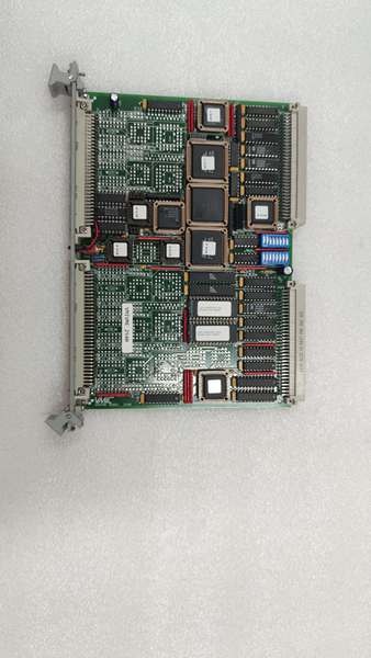
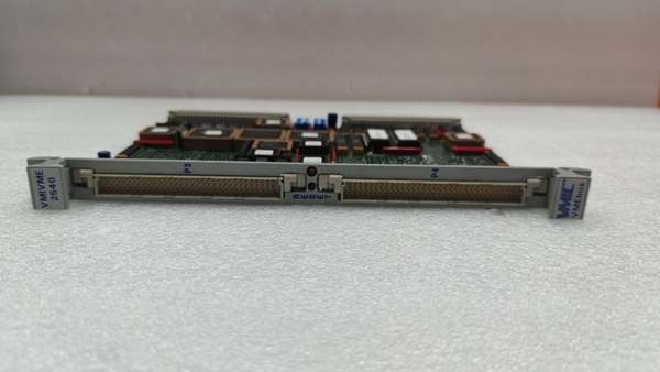
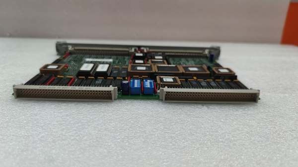
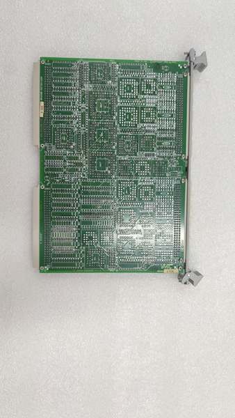
VMIVME-2540-000
The Real-World Problem It Solves
Separate counter cards and external PLCs add latency, cost, and cabinet space for high-speed pulse/encoder monitoring. Discrete counters lack synchronization and real-time processing needed for turbine speed and flow control.
Where you’ll typically find it:
- GE Mark VI/VIe turbine control racks for shaft speed, gearbox vibration, and LVDT position monitoring
- Fossil power plant BOP cabinets for steam/gas flow, feedwater pump speed, and coal feeder pulse counting
- Refinery DCS racks for process flow meter (pulse output) and motor encoder position tracking
Bottom line: It integrates 24 high-speed counters/encoders and pulse generation on one VME card to eliminate external hardware and reduce measurement latency.
Hardware Architecture & Under-the-Hood Logic
This board is a VMEbus slave with an onboard 68HC000 CPU, dedicated counter/timer ICs, and differential line receivers for high-noise industrial environments.
- VME host downloads channel config (count/freq/quadrature/pulse gen) to onboard CPU.
- Differential/TTL I/O circuits condition incoming pulses/encoder signals to logic levels.
- Dedicated 32-bit counters/timers process signals independently (no VME bus latency).
- Onboard CPU runs measurement algorithms, logs data to shared memory, and manages interrupts.
- VME host reads processed data (count, freq, position) or sets pulse generation parameters.
Field Service Pitfalls: What Rookies Get Wrong
Overlooking Signal Ground IsolationNew techs tie I/O signal ground to VME logic ground. Common-mode noise from motor drives/relays corrupts low-level pulse/encoder signals, causing erratic counts or position jumps.
- Field Rule: Isolate signal ground from VME chassis/logic ground; use differential signaling for >10ft cable runs.
Inadequate Cable Shield TerminationRookies ground shield at both ends or leave it floating. Ground loops or EMI induce noise on high-frequency (≥100kHz) signals, leading to missing counts or frequency errors.
- Quick Fix: Terminate shield at the card end only; use twisted-pair shielded cable (Belden 8761 or equivalent) for all I/O.
Misconfiguring Quadrature Encoder ChannelsTechs set wrong pulse/rev count or disable limit checking. This causes position rollover, lost motion, or false “position fault” trips in turbine/actuator control.
- Field Rule: Match encoder PPR to config; enable 32-bit limit/modulo checking; test with known position before startup.
VMIVME-2540-000
Commercial Availability & Pricing Note
Please note: The listed price is for reference only and is not binding. Final pricing and terms are subject to negotiation based on current market conditions and availability.


