
Description
Key Technical Specifications
-
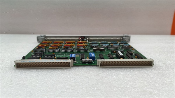
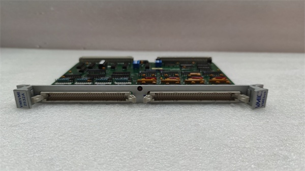
Model Number: VMIVME-2534
-
Manufacturer: GE (ex-VMIC)
-
I/O Count: 32 bits, jumpered per 8-bit nibble as input or output
-
Output Driver: UDN2549B darlington, 600 mA sink, 60 V breakdown
-
Over-Current: 1 A per channel with thermal-limit fold-back
-
Clamp: Integral 60 V clamp diodes on all outputs
-
Input Threshold: Jumper-select 1.25 – 60 V (open-circuit = logic 0 or 1)
-
Filtering: On-board RC per channel, jumper-enable
-
BIT: Real-time open-wire / shorted-driver sense, front-panel FAIL LED
-
Isolation: 500 V channel-to-bus (opto)
-
Connectors: Front-panel 96-pin DIN 41612; rear I/O via P2
-
Power: +5 V @ 1.2 A (all outputs on), +12 V 50 mA for BIT
-
Form Factor: 6U single-slot VME slave, A16/A24, D08/D16

GE VMIVME-2532A
Field Application & Problem Solved
Power-plant auxiliary skids still run mixed voltages—12 V pilot lights, 24 V solenoids, 48 V battery trips—and the DCS needs to drive them and read position feedback without adding three different cards. VMIVME-2534 gives you 32 lines that can be split any way you want: nibble-by-nibble jumper sets direction, threshold, and pull-up logic.
Power-plant auxiliary skids still run mixed voltages—12 V pilot lights, 24 V solenoids, 48 V battery trips—and the DCS needs to drive them and read position feedback without adding three different cards. VMIVME-2534 gives you 32 lines that can be split any way you want: nibble-by-nibble jumper sets direction, threshold, and pull-up logic.
I’ve hung this card on a black-start diesel package: 24 outputs driving 48 V fuel-trip solenoids, 8 inputs reading 12 V limit-switch status. The integral 60 V clamp ate the flyback from the coils and the BIT flag caught a shorted driver before we ever hit START—saved a false trip on day-one.
Core value: one slot replaces thirty-two relays and thirty-two status inputs, while the on-card protection keeps inductive spikes off the backplane.
Installation & Maintenance Pitfalls (Expert Tips)
Direction jumpers are nibble-based
Channels 0-7, 8-15, 16-23, 24-31 each need a jumper block set to IN or OUT. Miss one and you’ll read back garbage or blow the driver. Label the silk-screen map on the panel door so the next guy doesn’t chase “bad inputs” for an hour.
Channels 0-7, 8-15, 16-23, 24-31 each need a jumper block set to IN or OUT. Miss one and you’ll read back garbage or blow the driver. Label the silk-screen map on the panel door so the next guy doesn’t chase “bad inputs” for an hour.
Over-current is fold-back, not fuse
The 1 A thermal limit folds current back to ~200 mA until temperature drops. If your valve coil inrushes 1.5 A it will never fully energize—add an external interposing relay or size the coil under 500 mA steady-state.
The 1 A thermal limit folds current back to ~200 mA until temperature drops. If your valve coil inrushes 1.5 A it will never fully energize—add an external interposing relay or size the coil under 500 mA steady-state.
Input open-circuit sense is jumper-select
Open wire can read logic 0 or 1 depending on JP18. Set it to the safe state (usually 0 = fault) and wire your limit switches normally-closed so a broken wire looks like a trip.
Open wire can read logic 0 or 1 depending on JP18. Set it to the safe state (usually 0 = fault) and wire your limit switches normally-closed so a broken wire looks like a trip.
Clamp diode is internal—do not add external diode
Adding a 1N4007 across the load creates a dual-path clamp that splits current and overheats the driver. Trust the on-chip 60 V diode; if you need faster turn-off, add a zener across the coil, not a standard diode.
Adding a 1N4007 across the load creates a dual-path clamp that splits current and overheats the driver. Trust the on-chip 60 V diode; if you need faster turn-off, add a zener across the coil, not a standard diode.
Front-panel FAIL LED is latched
FAIL LED stays on until you read the BIT register—handy for catching intermittent faults, but it also masks new faults if you never clear it. Read the register during every scan and log the nibble; otherwise you’ll miss the second failure.
FAIL LED stays on until you read the BIT register—handy for catching intermittent faults, but it also masks new faults if you never clear it. Read the register during every scan and log the nibble; otherwise you’ll miss the second failure.
GE VMIVME-2532A
Technical Deep Dive & Overview
The 2534 is a 32-bit VME register driving opto-isolated UDN2549B high-voltage darlington arrays. Each channel can sink 600 mA at 60 V and survives inductive kick via on-chip clamp diodes. A 22V10 PLD decodes VME cycles, latches data, and returns BIT status; no firmware means nothing to corrupt. Because direction is set per 8-bit nibble, you can mix high-current outputs and high-threshold inputs on the same connector—saving panel space and eliminating the relay nest that always welds shut at the worst moment.
The 2534 is a 32-bit VME register driving opto-isolated UDN2549B high-voltage darlington arrays. Each channel can sink 600 mA at 60 V and survives inductive kick via on-chip clamp diodes. A 22V10 PLD decodes VME cycles, latches data, and returns BIT status; no firmware means nothing to corrupt. Because direction is set per 8-bit nibble, you can mix high-current outputs and high-threshold inputs on the same connector—saving panel space and eliminating the relay nest that always welds shut at the worst moment.


