
Description
Key Technical Specifications
-
Model Number: VMIVME-2528
-
Manufacturer: GE (legacy VMIC)
-
I/O Count: 128 TTL lines, grouped as sixteen 8-bit ports
-
Port Control: Individual jumper per 8-bit port = input or output
-
Drive: 24 mA sink / 6.5 mA source per line
-
Logic: High-true or low-true (jumper)
-
Data Transfer: 8- or 16-bit VME D16 cycles, A16 short I/O map
-
Connectors: 64-pin DIN 41612 front; alternating ground pins for SI
-
Power: +5 V @ 3 A max (all outputs loaded)
-
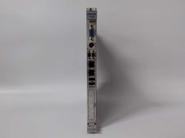
Form Factor: 6U double-Euro, single-slot VME slave
-
Temp: 0 – 55 °C operating, –20 – +85 °C storage

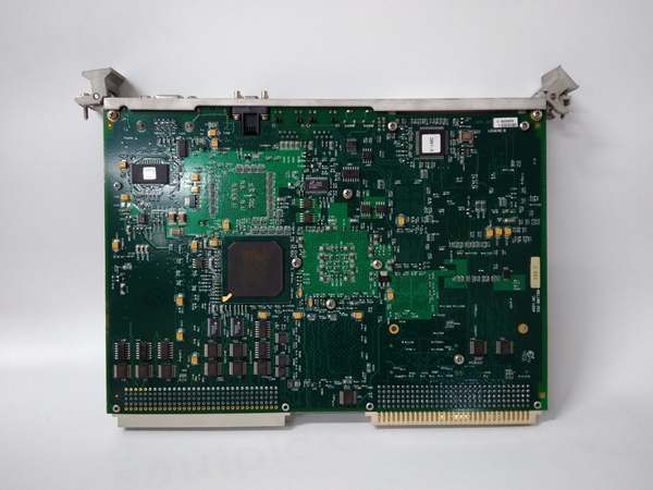
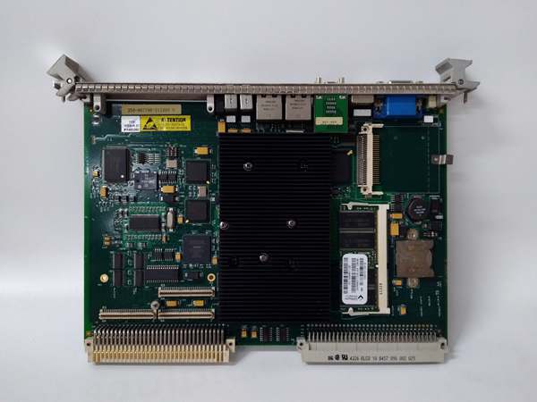
GE VMIVME-7700RC
Field Application & Problem Solved
Gas-turbine panels eat TTL lines—blade-tip timing, valve-position feedback, annunciator lamps, purge-complete flags. Old racks needed four 32-bit cards and a fistful of ribbon cable. Slide in one VMIVME-2528 and you just flattened the problem: 128 TTL bits in one slot, each 8-bit port software-steered as input or output, and the alternating-ground pinout keeps switching noise from crawling into the adjacent clock line.
Gas-turbine panels eat TTL lines—blade-tip timing, valve-position feedback, annunciator lamps, purge-complete flags. Old racks needed four 32-bit cards and a fistful of ribbon cable. Slide in one VMIVME-2528 and you just flattened the problem: 128 TTL bits in one slot, each 8-bit port software-steered as input or output, and the alternating-ground pinout keeps switching noise from crawling into the adjacent clock line.
I’ve used this exact card on a 7FA turbine package: 64 outputs driving opto-isolators for trip relays, 64 inputs reading 5 V position sensors. The 24 mA sink let me drive the optos directly—no intermediate buffer—while the low-true jumper option made the safety logic “off = 1” so a broken wire looked like a trip. Core value: relay-rack density without the relays; one read-modify-write and you’ve strobed an entire annunciator window.
Installation & Maintenance Pitfalls (Expert Tips)
Port direction is jumper-hard
Each 8-bit port is steered by a physical jumper block. Forget to move it and you’ll short a TTL output straight into a sensor pull-up—blow the driver and the whole port goes dark. Label the silk-screen map on the panel door so the next guy doesn’t chase “dead bits” for an hour.
Each 8-bit port is steered by a physical jumper block. Forget to move it and you’ll short a TTL output straight into a sensor pull-up—blow the driver and the whole port goes dark. Label the silk-screen map on the panel door so the next guy doesn’t chase “dead bits” for an hour.
24 mA is sink only—no high side
The card sources a weak 6.5 mA. If your opto LED needs 10 mA forward you must wire it sink-side (card pulls low) or add an external PNP buffer. Otherwise the LED glows dim and the operator thinks the valve is half-open.
The card sources a weak 6.5 mA. If your opto LED needs 10 mA forward you must wire it sink-side (card pulls low) or add an external PNP buffer. Otherwise the LED glows dim and the operator thinks the valve is half-open.
Power-on state is tri-state
Board releases tri-state after the first write to any port. If your safety logic expects outputs low at boot, add a pull-down resistor pack or write zeros in the boot script before enabling field supplies—prevents spurious trips during CPU restart.
Board releases tri-state after the first write to any port. If your safety logic expects outputs low at boot, add a pull-down resistor pack or write zeros in the boot script before enabling field supplies—prevents spurious trips during CPU restart.
Alternating grounds are signal integrity
Pins 2,4,6… are ground. If you crimp a 64-pin connector without them, crosstalk on fast edges (≤5 ns) will toggle adjacent inputs. Use the recommended Panduit 120-964-435E connector and keep twist lengths under 1 cm.
Pins 2,4,6… are ground. If you crimp a 64-pin connector without them, crosstalk on fast edges (≤5 ns) will toggle adjacent inputs. Use the recommended Panduit 120-964-435E connector and keep twist lengths under 1 cm.
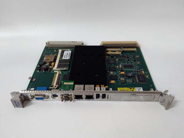
GE VMIVME-7700RC
3 A is real
All 128 outputs loaded at 24 mA = 3 A on the +5 V rail. Verify your VME supply can source it; otherwise the rail sags to 4.7 V and random TTL levels creep into the unknown region—looks like “intermittent logic.”
All 128 outputs loaded at 24 mA = 3 A on the +5 V rail. Verify your VME supply can source it; otherwise the rail sags to 4.7 V and random TTL levels creep into the unknown region—looks like “intermittent logic.”
Technical Deep Dive & Overview
The 2528 is nothing more than 128 TTL transceivers tied to a VME D16 slave interface. A 22V10 PLD decodes short I/O addresses, drives direction latches, and asserts DTACK in <100 ns. Because each 8-bit port is individually jumpered, you can reshape the card on the fly—no firmware, no scan list, just copper and logic. The alternating-ground pinout and low-inductance plane give you clean 5 ns edges at 24 mA, fast enough to bit-bang a 2 MHz SPI if you’re desperate. Simple, dense, and bullet-proof—exactly what you want when the turbine wants 128 bits of status yesterday.
The 2528 is nothing more than 128 TTL transceivers tied to a VME D16 slave interface. A 22V10 PLD decodes short I/O addresses, drives direction latches, and asserts DTACK in <100 ns. Because each 8-bit port is individually jumpered, you can reshape the card on the fly—no firmware, no scan list, just copper and logic. The alternating-ground pinout and low-inductance plane give you clean 5 ns edges at 24 mA, fast enough to bit-bang a 2 MHz SPI if you’re desperate. Simple, dense, and bullet-proof—exactly what you want when the turbine wants 128 bits of status yesterday.


