
Description
Hard-Numbers: Technical Specifications
- Channel Count: 64 relay outputs, independent SPDT (NO/NC/Common)
- Relay Type: Magnetic latching (remains set/reset without power)
- Contact Rating: 2A @ 250VAC / 220VDC per channel, 60W max
- VME Bus Protocol: VMEbus Rev C.1, A16/A24, D08/D16/D32 slave
- Data Transfer: 8/16/32-bit, relay state readback supported
- Operating Temperature: 0°C to +60°C (industrial)
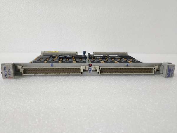
- Onboard Diagnostics: BIT self-test, fault readback registers, no front LED
- Power Draw: 8W typical, 1.6A @ 5VDC backplane power
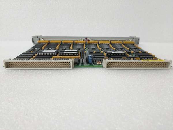
- Connectors: Dual 96-pin DIN (P1/P2) for field wiring
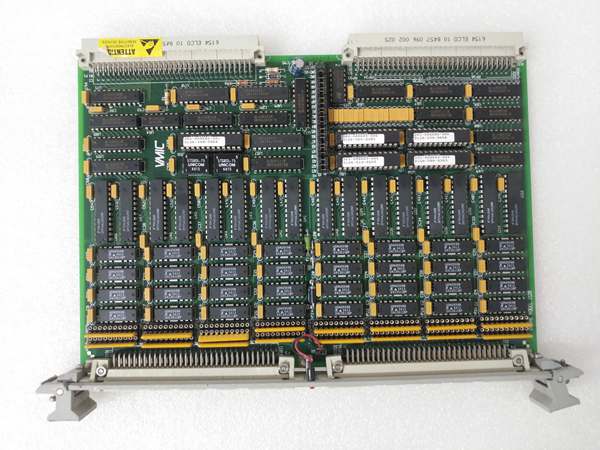
GE VMIVME-2128
The Real-World Problem It Solves
Standard non-latching relays drop out during power glitches or maintenance, triggering false trips in safety systems. External relay panels add cost, space, and wiring complexity in power plants and refineries.
Where you’ll typically find it:
- GE Mark VI/VIe turbine control racks for ESD, trip, and fuel valve interlock relays
- Fossil power plant safety systems for breaker trip, emergency stop, and critical alarm circuits
- Refinery DCS racks for SIL-rated interlock and process shutdown relay control
Bottom line: It delivers 64 latching, fail-safe relays in one VME slot to eliminate external panels and prevent power-loss false trips.
Hardware Architecture & Under-the-Hood Logic
This board is a VMEbus slave with no local processor, using magnetic latching relays and dedicated BIT logic for safety-critical control.
- VME controller writes set/reset commands to onboard relay driver registers.
- Drivers pulse coil windings to latch or unlatch magnetic relay contacts.
- Relay contacts switch field circuits (NO/NC/Common) independent of card power.
- BIT logic monitors coil drive and contact state; compares to command in real time.
- VME bus reads back relay status and BIT fault codes for diagnostics.
GE VMIVME-2128
Field Service Pitfalls: What Rookies Get Wrong
Confusing Latching vs. Non-Latching OperationNew techs treat latching relays like standard momentary types—they forget to reset latched states after trips. This leaves safety circuits in a dangerous “stuck” condition.
- Field Rule: Always write explicit reset logic in the DCS; verify all relays reset during startup checkout.
Overloading Contacts With Inductive LoadsRookies wire 24VDC contactors or solenoids directly to relays without snubbers. Inductive kickback burns contacts fast, leading to stuck-open or shorted channels.
- Quick Fix: Derate to 1.5A max for inductive loads; add RC snubbers (100Ω/0.1μF) across coils.
Ignoring BIT Faults as “Nuisance Alarms”Techs clear BIT faults without investigating. Most faults stem from broken coil wires, worn contacts, or miswired fields—ignoring them leads to silent safety failures.
- Field Rule: Log and investigate every BIT fault; replace relays with >100k cycles or intermittent state errors.
Commercial Availability & Pricing Note
Please note: The listed price is for reference only and is not binding. Final pricing and terms are subject to negotiation based on current market conditions and availability.


