
Description
Hard-Numbers: Technical Specifications
- Channel Count: 128 digital input points, grouped in 16 banks of 8
- Input Voltage Range: 1.25 VDC to 66 VDC
- Isolation Rating: 1500V channel-to-backplane galvanic isolation
- VME Bus Protocol: VMEbus Rev C.1, A16/A24 addressing, D08/D16/D32 slave
- Input Type: Jumper selectable sinking or sourcing per bank
- Operating Temperature: -20°C to +70°C continuous rated
- Onboard Diagnostics: Built-in BIT self-test circuitry and front panel fault LED
- Power Draw: 11.55W typical, 2.31A @ 5 VDC backplane power
- Connector Type: Front panel heavy-duty terminal block for field wiring
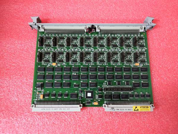
VMIVME-1128
The Real-World Problem It Solves
Standard low-voltage VME input cards cannot handle 24VDC and 48VDC field contact signals common in power plants and refineries. Mixing external signal conditioners adds wiring clutter, ground loops, and unplanned contact chatter.
Where you’ll typically find it:
- GE Mark VI and Mark VIe gas and steam turbine safety and auxiliary I/O racks
- Fossil and combined-cycle power plant balance-of-plant discrete monitoring cabinets
- Refinery and chemical process DCS racks for valve limit, E-stop, and interlock contact inputs
Bottom line: It delivers high-channel-count, high-voltage isolated sensing in a single dual-width VME slot to eliminate external signal conversion hardware.
Hardware Architecture & Under-the-Hood Logic
This board operates as a VMEbus slave I/O device with no local processor, relying on isolated optocoupler circuitry to separate noisy field wiring from clean control backplane voltage.
- Field discrete contacts feed voltage to banked opto-isolators for galvanic separation.
- Isolated signal conditioning circuits debounce raw contact inputs to filter field noise.
- Buffered digital states latch into onboard register arrays for VME bus polling.
- Backplane VME addressing allows the system controller to read channel status in real time.
- Integrated BIT logic runs continuous health checks and triggers the front panel fault LED on hardware failure.
VMIVME-1128
Field Service Pitfalls: What Rookies Get Wrong
Incorrect Bank Jumper ConfigurationNew techs skip bank-by-bank jumper setup, mixing sinking and sourcing modes across grouped channels. Mismatched settings produce floating inputs and false interlock trips during vibration.
- Field Rule: Configure each 8-channel bank to match field sensor type; document jumper positions on the card edge label.
Overlooking Common Mode Voltage StressUnbalanced field grounding pushes excessive common-mode voltage across unisolated wiring runs. Over time, this degrades optocouplers and creates intermittent channel dropout.
- Quick Fix: Use isolated field cable shields bonded at one end only; never cross ground references between cabinet and field junction boxes.
Ignoring BIT Fault AlarmsRookies clear fault LEDs without investigation, ignoring marginal input voltage drift on aging contact circuits. Unaddressed drift leads to hidden interlock failure points.
- Field Rule: Lock out and test any channel flagged by BIT; replace corroded contacts or frayed wiring before resetting diagnostics.
Commercial Availability & Pricing Note
Please note: The listed price is for reference only and is not binding. Final pricing and terms are subject to negotiation based on current market conditions and availability.


