
Description
Hard-Numbers: Technical Specifications
- Series: GE Multilin UR Series Universal Relays
- Manufacturer: General Electric (GE) / Emerson (post-acquisition)
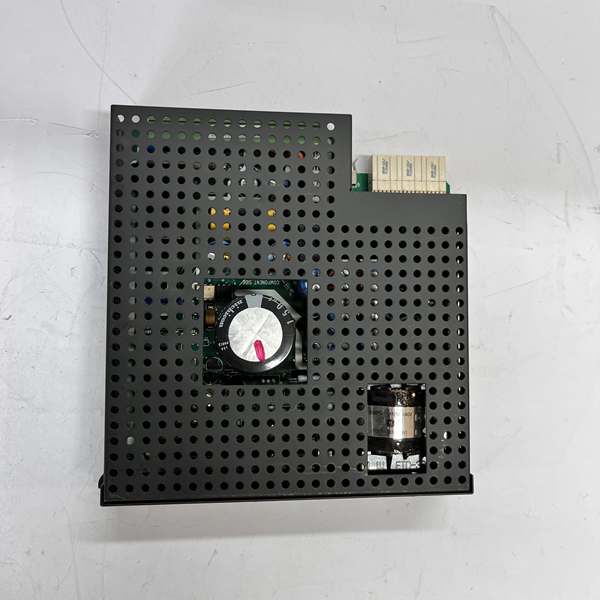
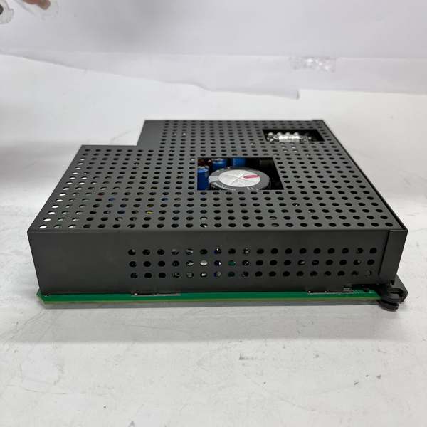
- Module Type: Power Supply Module (Horizontal Unit)
- Voltage Range Options:
- Low Range (LO): 24 to 48 V nominal (DC only)
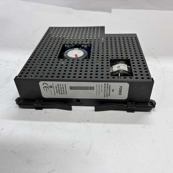
- High Range (HI): 125 to 250 V nominal (AC and DC compatible)
- Input Voltage Specifications:
- AC Range: 100-240 VAC
- DC Range (Low): 12-48 VDC
- DC Range (High): 125-250 VDC
- Output Power: 35 Watts typical (High Range), 35VA at AC input
- Internal Fuse Rating: 4A / 250 V
- Operating Temperature Range: -20°C to +70°C (-4°F to +158°F)
- Storage Temperature Range: -40°C to +85°C (-40°F to +185°F)
- Humidity Tolerance: 0-95% RH non-condensing
- Dimensions: Approximately 215 mm × 115 mm × 50 mm (varies by source)
- Weight: 0.286 kg to 0.62 kg (varies by source/configuration)
- Protection Features: Overcurrent, short circuit, overvoltage protection via internal fuse and electronics
- Certifications: UL, CE, CSA, C-UL (varies by configuration)
- Safety Compliance: IEC 61508 SIL 3, ISO 13849 PLe (for configured systems)
- Redundancy: Optional N+1 redundancy configuration available (parallel operation with automatic switchover)
- LED Indicators:
- Continuous ON: Normal operation
- ON/OFF Cycling: Warning/Failure condition
- OFF: No power or complete failure
- Self-Testing: Major and minor self-test routines integrated into relay diagnostic system
- Environmental Classification: Pollution Degree 2 environments
- Status: Manufacturer discontinued (some sources indicate discontinued status)
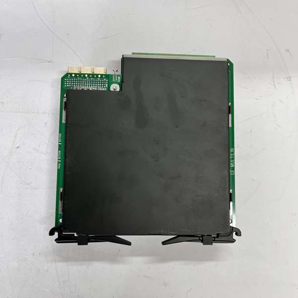
GE URRHH
The Real-World Problem It Solves
Power protection relays require stable, reliable power to ensure continuous monitoring and fast fault response in critical electrical infrastructure. Power interruptions can cause relay dropout, delayed fault detection, and compromised system protection. The URRHH provides a wide input voltage range (24-250V AC/DC) to accommodate global power standards, optional redundancy for zero-downtime operation, and built-in self-diagnostics with LED status indication. This ensures UR series relays maintain protection function even during input voltage fluctuations or single power supply failures.
Where you’ll typically find it:
- High-voltage transmission line protection (L90 line differential relays)
- Generator protection systems (G60 generator protection relays)
- Motor protection in industrial facilities (M60 motor management relays)
- Substation and switchyard protection panels
- Marine and offshore electrical distribution systems
Bottom line: It delivers reliable, redundant-capable power for UR series protection relays with comprehensive diagnostics and wide voltage compatibility, ensuring continuous protection function in critical electrical infrastructure.
Hardware Architecture & Under-the-Hood Logic
The URRHH converts wide-range input AC/DC voltage into regulated DC power required by UR series relay modules and associated dry contact inputs.
-
Input Stage:
- Wide-Range Input: Accepts 24-48 VDC (Low Range) or 100-240 VAC / 125-250 VDC (High Range).
- Overcurrent Protection: Internal 4A/250V fuse provides backup protection against catastrophic faults.
- Inrush Current Limiting: Soft-start circuitry limits inrush current during power-up to protect upstream circuits.
-
Power Conversion:
- Switching Regulator: High-efficiency switching topology converts input voltage to regulated intermediate DC voltage.
- Regulation: Precision voltage regulation maintains stable output under varying load conditions and input voltage fluctuations.
- Filtering: EMI/RFI filtering reduces noise on both input and output, ensuring clean power for sensitive relay electronics.
-
Redundancy Operation (Optional):
- Parallel Configuration: Two URRHH modules can be installed in parallel for N+1 redundancy.
- Automatic Switchover: If one power supply fails, the other assumes full load without interruption.
- Fault Isolation: Failed supply isolates itself, preventing it from affecting the operational unit.
-
Output Distribution:
- Relay Power: Provides primary DC power to the UR series relay main processor and I/O circuits.
- Dry Contact Power: Supplies power for dry contact input connections, enabling external device monitoring.
- Current Limiting: Electronic current limiting prevents damage during output overload conditions.
-
Diagnostics and Self-Testing:
- Major Self-Test: Comprehensive test of power supply integrity, voltage regulation, and fuse status.
- Minor Self-Test: Quick check of critical parameters during normal operation.
- LED Indication: Front panel LEDs communicate status directly to operators:
- Continuous ON: Normal operation, all parameters within specifications
- ON/OFF Cycling: Warning condition, self-test detected hardware issue or critical failure
- OFF: No power input or complete power supply failure
- CPU Communication: Fault conditions are reported to relay CPU for logging and remote notification via communication protocols (Modbus TCP/IP, DNP3.0, IEC 61850, etc.).
-
Environmental Protection:
- Conformal Coating: Available option for harsh environments (humidity, corrosive atmospheres).
- Thermal Management: Design allows operation from -20°C to +70°C with derating above specified thresholds.
- Dust Resistance: Enclosure design complies with Pollution Degree 2 requirements.
-
Installation and Integration:
- Module Mounting: Installs horizontally in UR series relay chassis.
- Hot-Swappable: Allows module replacement without powering down the entire relay system (in redundant configurations).
- EnerVista UR Software Integration: Supports remote monitoring and diagnostics via GE’s EnerVista UR configuration software.
GE URRHH
Field Service Pitfalls: What Rookies Get Wrong
Incorrect Voltage Range SelectionInstallers select the wrong voltage range (LO vs HI) during installation, causing the power supply to fail to start or operate outside specifications.
- Field Rule: Always verify the site’s available power source before ordering. Use LO range (24-48VDC) for low-voltage DC systems; use HI range (100-240VAC / 125-250VDC) for standard AC or high-voltage DC applications.
Redundancy MisconfigurationTechnicians install two URRHH modules but fail to configure them for parallel operation, or use non-redundant modules where redundancy is required.
- Quick Fix: Ensure both power supplies are redundancy-configured versions. Verify parallel wiring per the UR series installation manual. Confirm that the relay system is configured to recognize and switch between redundant power sources.
Ignoring LED Status IndicationsField personnel misinterpret or ignore the LED indicators (Continuous ON, ON/OFF Cycling, OFF), missing early warnings of impending power supply failure.
- Field Rule: Establish a routine to check LED status during regular maintenance inspections. ON/OFF Cycling indicates a warning condition that should be investigated immediately—do not wait for complete failure. OFF indicates no input power or catastrophic failure.
Overloading the Power SupplyEngineers add additional relay modules or external devices without calculating total power draw, exceeding the 35W rating and causing thermal shutdowns or reduced reliability.
- Quick Fix: Calculate the total power consumption of all UR series modules and connected devices. Include headroom for inrush currents and future expansion. If load exceeds 35W, consider using multiple power supplies distributed across backplanes or higher-capacity options (e.g., UR series variants with 80W power).
Neglecting Temperature DeratingInstallers mount URRHH in hot enclosures without accounting for thermal derating, leading to overheating, Over Temperature LED activation, and premature failure.
- Field Rule: Verify ambient temperature at installation site. If operating near or above 60°C, provide adequate ventilation or consider external cooling. Consult the thermal derating curve in the manual for exact derating specifications.
Improper Grounding PracticesTechnicians create multiple ground references or fail to establish a common system ground, causing ground loops, noise, and erratic relay behavior.
- Field Rule: Establish a single-point ground reference for the entire UR series system. Connect the power supply ground terminal to the common system ground as specified. Avoid grounding shields at multiple points unless specifically required by the application.
Fuse Replacement with Wrong RatingMaintenance personnel replace the internal 4A/250V fuse with an incorrect rating (higher current or wrong voltage), compromising protection and potentially causing damage.
- Quick Fix: Always replace fuses with identical specifications: 4A / 250V. Using higher-current fuses defeats overcurrent protection and can cause catastrophic failure during fault conditions.
Sources:
- GE Multilin UR Series Product Documentation
- GE Power Supply Module Technical Specifications (URRHH / UR-RHH)
- EnerVista UR Software Documentation
- Industrial automation component suppliers (GK-DCS, 6G Controls, Aptor Power)
Please note: The listed price is for reference only and is not binding. Final pricing and terms are subject to negotiation based on current market conditions and availability.


