
Description
Hard-Numbers: Technical Specifications
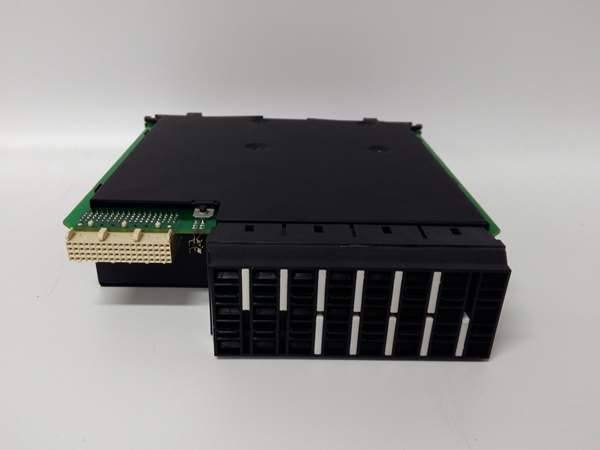
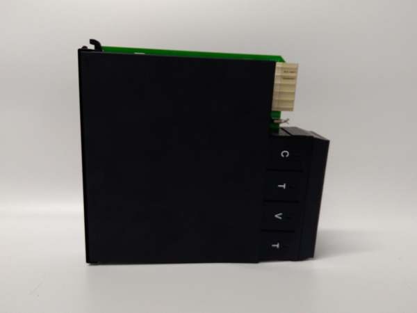
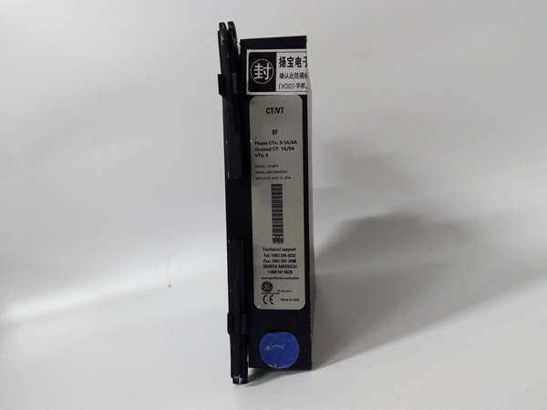
- CT Inputs: 4 channels (3 phase + 1 ground), configurable 1A or 5A nominal
- VT Inputs: 4 channels, line-line rated up to 300 VAC
- Frequency Range: 45–65 Hz (50/60 Hz nominal)
- Measurement Accuracy: ±0.2% (meets IEC 61869, IEEE C37.90)
- Isolation Rating: 2500 VAC between CT/VT and relay logic
- Operating Temperature: -40°C to +70°C continuous
- Power Draw: 6.2W max, powered from UR backplane
- Hot Swap: Live insertion/removal for in-service maintenance
- Termination: Spring-clamp terminals, accepts 14–22 AWG wire
- Dimensions: 4cm H × 18.5cm W × 17.2cm D
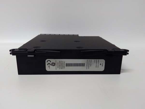
UR8FH
The Real-World Problem It Solves
Raw substation CT/VT outputs are too high for relay logic. Unscaled analog signals cause damage, inaccurate metering, and false trips from unisolated noise.
Where you’ll typically find it:
- Medium-voltage switchgear bays (5–35kV) for feeder/transformer protection
- Power plant generator and unit auxiliary transformer protection racks
- Industrial refinery motor control centers (MCC) with high-current loads
Bottom line: It safely steps down and isolates high-energy CT/VT signals, enabling accurate, noise-immune protection and metering.
Hardware Architecture & Under-the-Hood Logic
uses dedicated analog front-end (AFE) circuits per channel, independent of the main relay CPU. All CT/VT circuits have reinforced galvanic isolation.
- CT current (1/5A) and VT voltage inputs feed to isolated AFE stages.
- Precision burden resistors and op-amps scale signals to 0–5V logic levels.
- Onboard 16-bit ADCs convert analog signals to digital samples.
- Digital data passes across the isolated backplane to the host relay CPU.
- Per-channel diagnostics monitor signal range, saturation, and wiring faults.
Field Service Pitfalls: What Rookies Get Wrong
Incorrect CT Burden SettingsTechs mix 1A and 5A CT taps without reconfiguring the module. Mismatched burden causes saturation, inaccurate readings, and misoperation.
- Field Rule: Match module CT setting (1A/5A) to the physical CT tap; verify via EnerVista before energizing.
Loose VT Wiring & GroundingPoor spring-clamp torque or missing VT ground connections introduce noise. Unstable voltage readings cause nuisance undervoltage/overvoltage trips.
- Quick Fix: Torque terminals to 0.8–1.0 Nm; bond VT secondary grounds to the station ground bus.
Overloading VT CircuitsParasitic loads (extra meters, recorders) on VT terminals exceed module burden. Voltage distortion and phase angle error degrade protection accuracy.
- Field Rule: Limit VT secondary load to <50VA; use dedicated VT distribution blocks for multiple devices.
UR8FH
Commercial Availability & Pricing Note
Please note: The listed price is for reference only and is not binding. Final pricing and terms are subject to negotiation based on current market conditions and availability.

