
Description
Hard‑Numbers: Technical Specifications
- Digital Input Count: 4 optically isolated, dry contact/voltage rated
- Relay Output Count: 6 × Form‑A SPST electromechanical relays
- Input Voltage Range: 24/48/125/250 VDC software configurable
- Output Contact Rating: 5A resistive @ 250VAC / 30VDC
- Isolation Rating: 2500Vrms field‑to‑backplane galvanic isolation
- Operating Temperature: ‑40°C to +70°C continuous
- Power Draw: 3.6W max, backplane powered
- Input Filtering: 1ms–60s software debounce, noise rejection
- Response Time: <8ms input‑to‑backplane latency
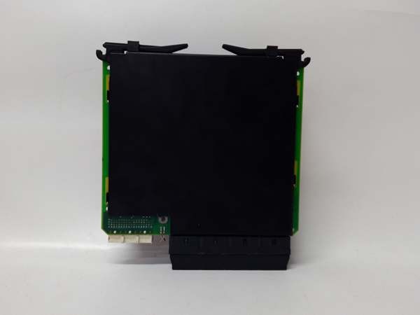
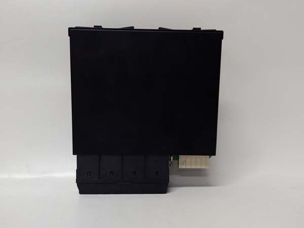
- Form Factor: Standard UR slot, hot‑swap capable
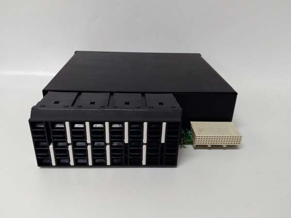
GE UR6PH
The Real‑World Problem It Solves
Base UR relays often need a small number of extra I/O points for alarms or auxiliary devices. Using a high‑density module wastes a slot; external relays add wiring and failure points.
Where you’ll typically find it:
- Substation bay control cabinets for alarm annunciation
- Generator protection panels for auxiliary sensor status
- Switchgear control racks for minor interlock and alarm circuits
Bottom line: It fills small I/O gaps with a single‑slot, low‑power, isolated solution to avoid external relays.
Hardware Architecture & Under‑the‑Hood Logic
uses a simple onboard logic chip, no dedicated CPU. All field circuits pass through opto‑isolation to block common‑mode noise and ground offsets.
- Field inputs go through current‑limiting resistors and 2500V optical isolation.
- Onboard logic debounces contacts and timestamps state changes.
- Filtered input data transmits across the UR backplane to the main relay.
- Main relay commands trigger isolated driver circuits to operate relay coils.
- Form‑A contacts switch load current; coils have basic surge suppression.
Field Service Pitfalls: What Rookies Get Wrong
Overloading Form‑A OutputsNew techs run 5A continuous on all six outputs. Contact wear accelerates, and coils overheat, causing random failures.
- Field Rule: Derate to 3A/channel max; avoid grouping all high‑current loads on this module.
Ignoring Input CommoningTechs mix different control voltage commons on the four inputs. Ground offsets create false “on” states with no physical contact closure.
- Field Rule: Use a single common per voltage group; separate 24VDC and 125VDC circuits.
Hot‑Swap Without Latch CheckTechs pull the module while energized without checking the latch. Partial insertion causes intermittent I/O loss and backplane errors.
- Quick Fix: Always fully seat and latch the module before applying power; hot‑swap only when main relay permits.

GE UR6PH
Commercial Availability & Pricing Note
Please note: The listed price is for reference only and is not binding. Final pricing and terms are subject to negotiation based on current market conditions and availability.


