
Description
Hard-Numbers: Technical Specifications
- Digital Input Count: 32 optically isolated, dry contact/voltage rated
- Digital Output Count: 16 × Form-A solid-state (SSR) outputs
- Input Voltage Range: 24/48/125/250 VDC software configurable
- Output Rating: 1A @ 250VAC / 30VDC per channel
- Isolation Rating: 2500Vrms field-to-backplane galvanic isolation
- Operating Temperature: -40°C to +70°C continuous
- Power Draw: 5.2W max, backplane powered
- Input Filtering: 1ms–60s software debounce, noise rejection
- Response Time: <5ms input-to-backplane latency
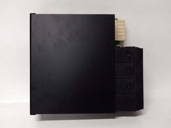
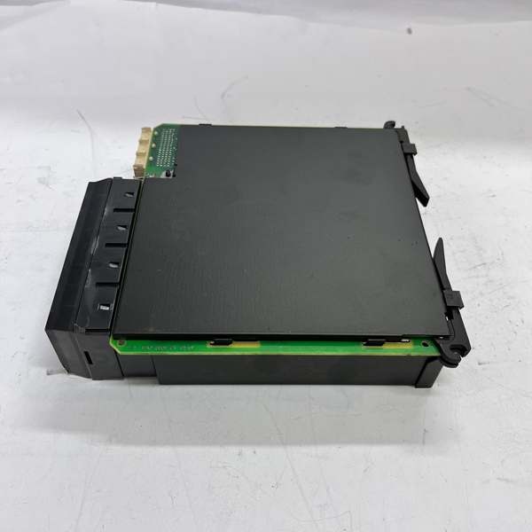
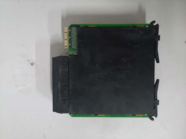
- Form Factor: Standard UR slot, hot-swap capable
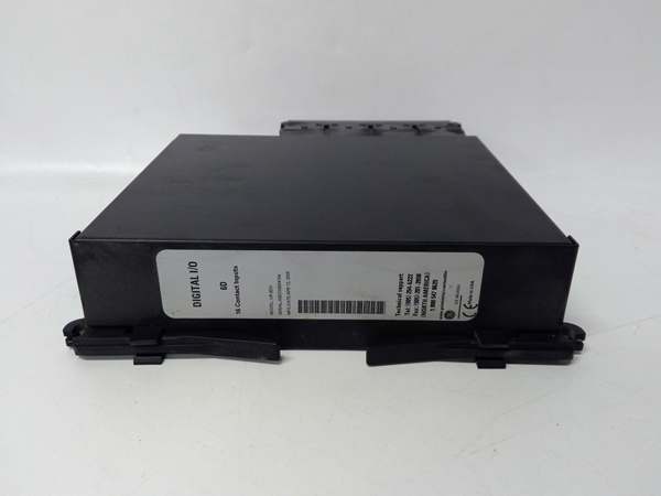
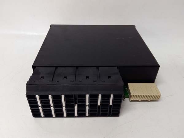
GE UR6DH
The Real-World Problem It Solves
Large substations and power plants blow past base relay I/O limits fast. External relay panels add hundreds of wires, extra terminations, and constant maintenance points.
Where you’ll typically find it:
- Transmission substation breaker control and bay interlock racks
- Combined-cycle plant generator trip and annunciator logic panels
- Refinery high-voltage switchgear protective relay assemblies
Bottom line: It packs 48 points of isolated I/O into one slot to eliminate external panels and cut field wiring by 60%+.
Hardware Architecture & Under-the-Hood Logic
uses a dedicated 32-bit onboard processor, independent of the main relay CPU. All field circuits pass through opto-isolation to block common-mode noise and ground offsets.
- Field inputs go through current-limiting resistors and 2500V optical isolation.
- Onboard processor filters bounce, timestamps changes, and flags faults locally.
- Clean input data transmits across the UR backplane to the main relay.
- Main relay commands pass through isolated drivers to solid-state output switches.
- Outputs switch load current; onboard MOVs suppress voltage spikes.
GE UR6DH
Field Service Pitfalls: What Rookies Get Wrong
Overloading Solid-State OutputsNew techs treat SSRs like mechanical relays, running 1A continuous on every channel. Heat builds up, de-rates the module, and causes random dropouts.
- Field Rule: Derate to 75% (0.75A/channel) at 60°C; avoid grouping all high-current loads on one module.
Ignoring Input Voltage GroupingMixing 24VDC and 125VDC inputs on adjacent banks creates leakage currents. False “on” states trigger with no physical contact closure.
- Field Rule: Isolate low/high voltage groups; use separate common rails for each voltage class.
Forcing Backplane InsertionMisaligned edge connectors get bent when jamming the card. Bent pins cause intermittent communication faults and module dropouts.
- Quick Fix: Align rails first; seat evenly until latch clicks—no brute force.
Commercial Availability & Pricing Note
Please note: The listed price is for reference only and is not binding. Final pricing and terms are subject to negotiation based on current market conditions and availability.


