
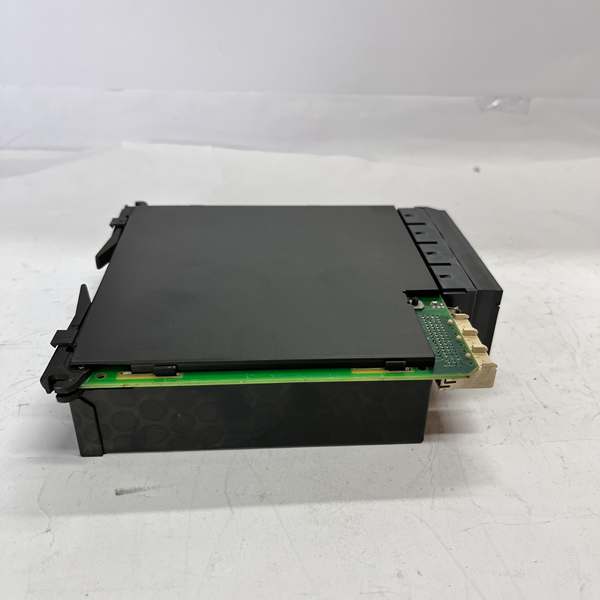
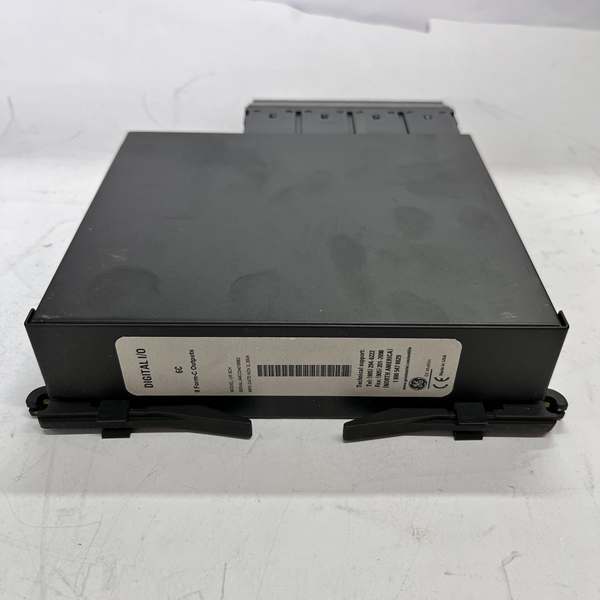
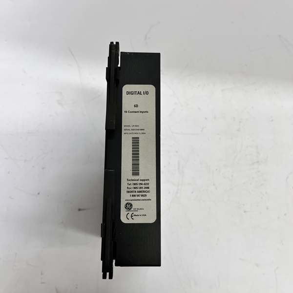
Description
Hard-Numbers: Technical Specifications
- CT Channel Count: 4 isolated current inputs (3-phase + core ground)
- VT Channel Count: 4 isolated AC voltage sensing inputs
- CT Nominal Rating: Software selectable 1A / 5A secondary
- Max VT Input: 300 VAC continuous line-to-line
- Operating Temperature: -40°C to +70°C ambient cabinet rating
- Isolation Rating: 2500Vrms reinforced isolation, field to backplane
- Maximum Power Draw: 7.4 Watts, backplane supplied
- Sample Resolution: 16-bit high-resolution ADC per analog channel
- Hot-Swap Capability: Live insert/remove with automatic CT shorting logic
- Measurement Accuracy: 0.1% full scale for ground fault metering
The Real-World Problem It Solves
Standard CT/VT modules clip low-magnitude leakage currents, letting developing ground faults go undetected in high-resistance grounded systems. Unaddressed insulation degradation leads to slow equipment failure and unplanned downtime.
Where you’ll typically find it:
- Generator step-up transformer bays at combined-cycle power plants
- Isolated and high-impedance grounded industrial distribution networks
- Remote transmission substations with minimal fault current availability
Bottom line: It delivers measurable low-current sensitivity standard analog modules cannot match, catching incipient insulation faults before they escalate.
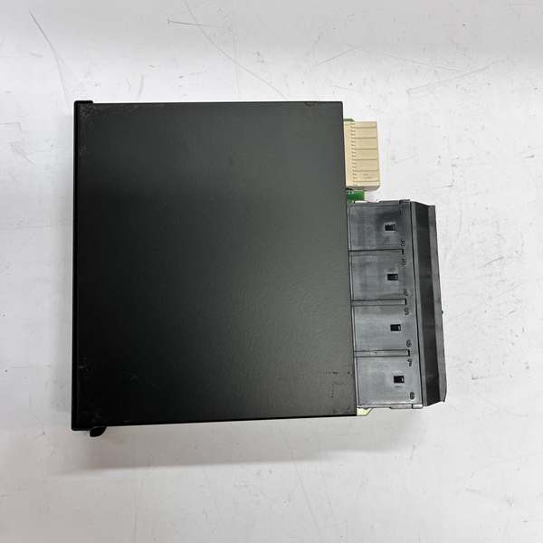
Hardware Architecture & Under-the-Hood Logic
UR-8HH uses independent high-gain analog front-end circuitry and a localized signal processor separate from the main relay CPU. Every field input path includes galvanic isolation to block common-mode noise and station ground offsets.
- Raw CT and VT secondary signals enter surge suppression and current-limiting networks.
- High-precision scaling amplifies weak ground fault currents without distorting phase measurements.
- Dedicated 16-bit ADC hardware converts all analog waveforms to clean digital data.
- Filtered, time-aligned sample data transfers across the isolated UR backplane to the host relay.
- Onboard diagnostic logic flags open CTs, degraded VT circuits, and abnormal signal saturation.
Field Service Pitfalls: What Rookies Get Wrong
Improper CT Polarity RoutingNew technicians rush CT wiring and reverse ground circuit polarity. Opposing current vectors cancel low-level fault flow and blind protection entirely.
- Field Rule: Mark and verify all H1/X1 polarity points; perform secondary injection testing before commissioning.
Overloaded VT Secondary CircuitsStacking multiple metering devices on the same VT branch adds excess burden. Heavy loading distorts low-resolution voltage samples and skews ground detection.
- Field Rule: Restrict auxiliary VT loads to under 30VA; use dedicated distribution blocks for multi-device setups.
Ignoring Cabinet Thermal LoadPacking full slot racks with high-density analog modules traps heat. Prolonged elevated operating temps drift calibration and shorten ADC service life.
- Quick Fix: Maintain side-to-side airflow gaps; clean cabinet filter baffles quarterly to reduce internal heat buildup.
Commercial Availability & Pricing Note
Please note: The listed price is for reference only and is not binding. Final pricing and terms are subject to negotiation based on current market conditions and availability.


