
Description
Hard-Numbers: Technical Specifications
- Fieldbus Standard: FOUNDATION Fieldbus H1 (IEC 61158-2)
- Fieldbus Ports: 2 × isolated FF H1 channels
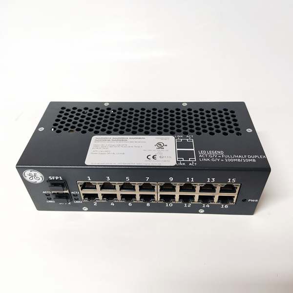
- Network Ports: 2 × 100 Mbps full-duplex IONet Ethernet
- Isolation Rating: 2500 Vrms field-to-backplane
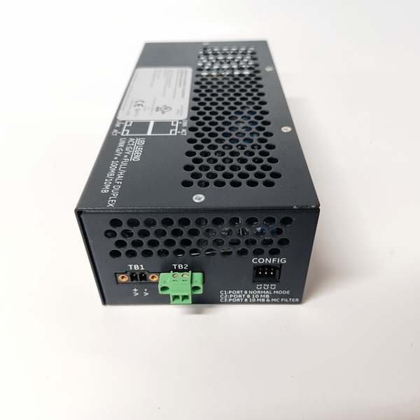
- Power Input: 18–32 VDC redundant
- Power Draw: 12 W typical
- Operating Temperature: -40°C to +70°C
- Shock/Vibration: IEC 60068-2-6, 5–2000 Hz, 2 g peak
- Environmental: Class I Div 2, Zone 2, G3 conformal coating
- Firmware: ControlST v07.01 or higher required
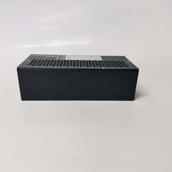
- Dimensions: Standard Mark VIe I/O pack (40 × 185 × 285 mm)
The Real-World Problem It Solves
Legacy 4–20 mA wiring creates signal drift, noise, and excessive termination labor in large process plants. This module digitizes field signals onto a digital two-wire bus, cutting wiring costs and improving measurement stability.
Where you’ll typically find it:
- Gas turbine fuel skids with FF H1 transmitters
- Refinery process units with pressure/temperature fieldbus instruments
- Offshore production modules with space-constrained marshalling cabinets
Bottom line: It replaces analog loops with a digital bus to reduce failures and simplify maintenance.
Hardware Architecture & Under-the-Hood Logic
This I/O pack uses a BPPC main processor with dedicated fieldbus controller ASICs. All field-side circuits are galvanically isolated to block ground loops.
- FF H1 frames are received from field transmitters via isolated transceivers.
- ASIC decodes fieldbus protocol and validates checksum.
- BPPC processor maps data to IONet memory registers for controller access.
- Dual Ethernet ports provide redundant communication to the control network.
- Front-panel LEDs indicate fieldbus activity, link status, and fault conditions.
Field Service Pitfalls: What Rookies Get Wrong
Fieldbus Ground Loop MiswiringTechs often ground both ends of the FF H1 shield. This creates circulating currents that corrupt communication and trigger intermittent dropouts.
- Field Rule: Ground the shield only at the I/O pack end; leave field end floating.
Incorrect Termination ResistorsMissing or duplicate 100 Ω termination resistors cause signal reflections and unstable communication. Rookies frequently install terminations on every device.
- Quick Fix: Install one 100 Ω resistor per FF H1 segment at the farthest device.
Undersized Fieldbus Power SupplyUsing a 24 VDC supply with insufficient current (less than 250 mA) starves multiple fieldbus devices. This leads to random transmitter timeouts.
- Field Rule: Use a dedicated, isolated FF H1 power supply rated ≥500 mA per segment.
Commercial Availability & Pricing Note
Please note: The listed price is for reference only and is not binding. Final pricing and terms are subject to negotiation based on current market conditions and availability.


