
Description
Hard-Numbers: Technical Specifications
- Standards: IEEE 802.3, 802.3u, 802.3x
- Copper Ports: 8× RJ45, 10/100 Mbps, auto-negotiation
- Fiber Port: 1× LC multi-mode, 100 Mbps FX
- Buffer: 256 KB minimum
- MAC Addresses: 4K table support
- Operating Temp: -40°C to +70°C
- Power Input: 24–28 VDC (redundant, diode-OR’d)
- Power Draw: ~12 W typical
- Isolation: 1500 Vrms port-to-bus
- Mounting: DIN-rail (BVP1/BVP4 clips)
- Weight: 0.9 kg
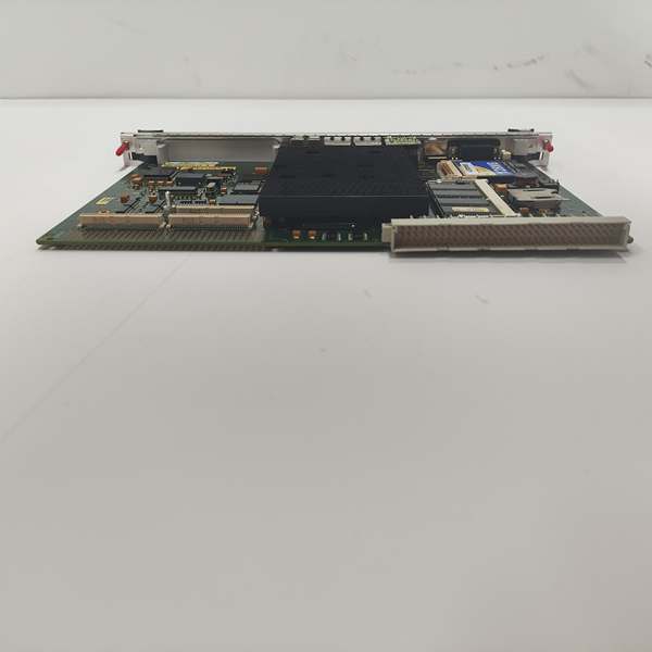
- Dimensions: 200 × 115 × 57 mm
The Real-World Problem It Solves
Control networks drop packets or lose comms when standard commercial switches fail in high-temperature, high-vibration environments. This unit delivers deterministic, low-latency switching for critical turbine I/O without lockups or faults.
Where you’ll typically find it:
- Mark VIe control cabinets in gas turbine power plants
- Steam turbine I/O networks in refineries and cogeneration facilities
- Offshore drilling rig turbine control networks
Bottom line: It keeps turbine control network traffic stable and fault-free in harsh industrial conditions.
Hardware Architecture & Under-the-Hood Logic
This switch operates as a managed layer 2 device on the Mark VIe IONet backplane with no host CPU dependency. It handles packet switching autonomously and maintains full electrical isolation between ports.
- Receives Ethernet frames from controller, I/O modules, and HMI clients.
- Filters and forwards packets based on MAC address table lookup.
- Applies flow control (802.3x) to prevent buffer overflow during traffic spikes.
- Transmits data over copper or fiber to target nodes with <1 ms latency.
- Monitors link status; triggers fault LEDs on loss of signal or voltage anomalies.
Field Service Pitfalls: What Rookies Get Wrong
Fiber Port LC Connector MismatchRookies force single-mode fiber into multi-mode LC ports. This causes high signal loss and intermittent link faults that are hard to diagnose with standard tools.
- Field Rule: Only use multi-mode fiber (50/125 or 62.5/125 µm) with ; verify fiber type before insertion.
Redundant Power Wiring MisconfigurationWiring both 24 VDC inputs to the same power source eliminates redundancy. The switch loses power entirely on a single supply failure.
- Quick Fix: Feed each power input from separate 24 VDC sources; use diode-OR design for true redundancy.
DIN-Rail Mount Orientation ErrorInstalling perpendicular to DIN rail without BVP2 clips leads to loose mounting. Vibration cracks internal solder joints and causes port failures.
- Field Rule: Use BVP1 clips for parallel mounting; BVP2 clips only for perpendicular orientation.
Commercial Availability & Pricing Note
Please note: The listed price is for reference only and is not binding. Final pricing and terms are subject to negotiation based on current market conditions and availability.


