
Description
Hard-Numbers: Technical Specifications
- Input Channels: 24× discrete contact inputs (18–32 VDC wetting)
- Output Channels: 12× Form-C relay outputs (5A @ 250VAC / 30VDC)
- Isolation: 2500VAC field-to-backplane; channel-to-channel isolated
- Power Input: 24 VDC (18.5–32 VDC), 10 W max
- Relay Life: ≥10M mechanical, ≥100K electrical (full load)
- Response Time: Input ≤10ms, Output ≤5ms
- Temp: -40°C to +70°C; Humidity 5–95% (non-condensing)
- Dimensions: 233 × 150 × 64 mm; Weight: 1.5 kg
- Mount: 35mm DIN-rail
- Cert: UL, CE, Class I Div 2, ATEX Zone 2
- Protection: Over-voltage, surge suppression, reverse polarity
The Real-World Problem It Solves
Turbine systems have hundreds of digital field signals (limit switches, solenoids, alarms). Uncontrolled wiring causes ground loops, EMI noise, and intermittent I/O faults. provides isolated, surge-protected termination with relay outputs to drive field loads safely.
Typical Applications:
- Gas/steam turbine valve position feedback
- Emergency stop (E-stop) and safety interlock circuits
- Pump starter and motor control signals
- Alarm annunciation and discrete status monitoring
Bottom line: stabilizes digital I/O and prevents noise-induced trips.
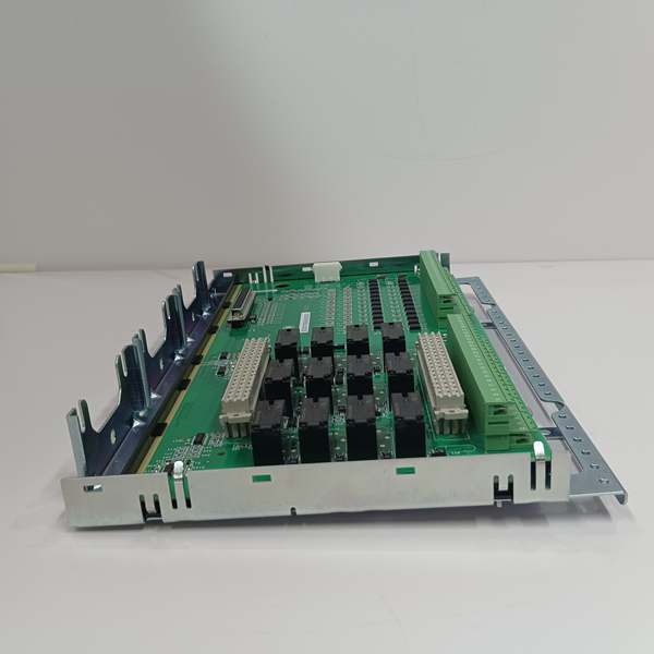
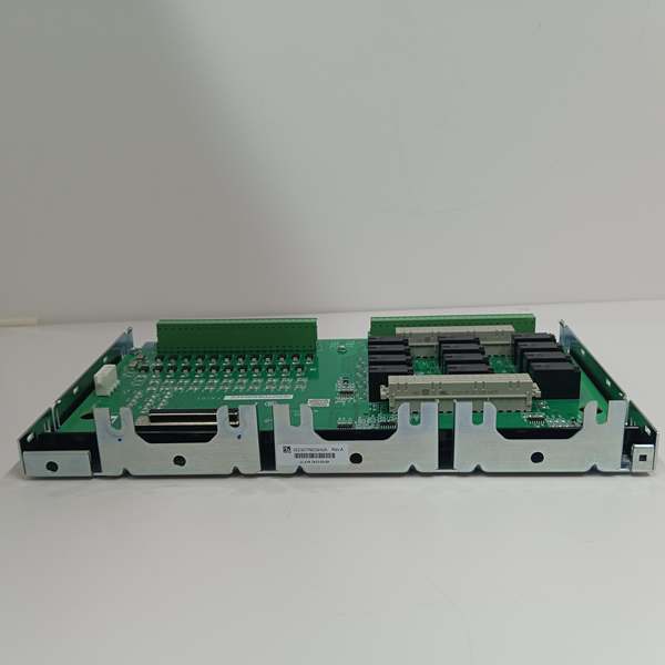
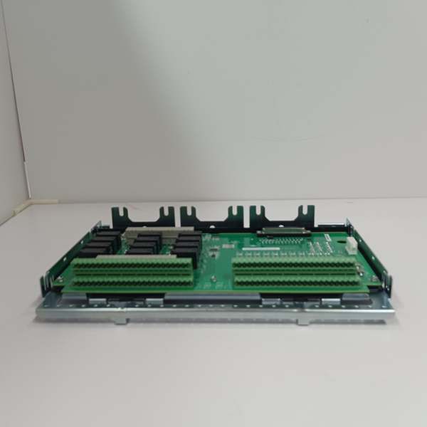
Hardware Architecture & Under-the-Hood Logic
is a passive-active interface with no microprocessor. It conditions and routes discrete signals:
- Field devices wire to pluggable euro-style terminals.
- Inputs: 24× isolated channels with surge/EMI filtering.
- Outputs: 12× Form-C relays driven by PDIO module signals.
- Galvanic isolation separates field grounds from control system.
- Status LEDs indicate input on/off, relay energized, power OK.
- Direct backplane connection to IS220PDIOH1B I/O pack.
- Over-voltage clamping protects against inductive load spikes.
Field Service Pitfalls: What Rookies Get Wrong
Under-sized Relay WiringUsing 22 AWG for 5A relay loads causes voltage drop and overheating.
- Field Rule: Use 18 AWG stranded for relay outputs; max 3m length.
Missing Surge Suppression on Inductive LoadsSolenoids/valves generate voltage spikes that destroy relay contacts.
- Quick Fix: Install flyback diodes (1N4007) or RC snubbers on all DC outputs.
Daisy-Chaining Input Wetting VoltageSingle power feed to all inputs creates common-mode failure risk.
- Field Rule: Split inputs into 2–3 groups; use separate 24 VDC sources.
Poor Grounding PracticesMixing field and cabinet grounds causes 5–20% signal error.
- Field Rule: Terminate shields ; float remote ends.
Commercial Availability & Pricing Note
Please note: The listed price is for reference only and is not binding. Final pricing and terms are subject to negotiation based on current market conditions and availability.


