
Description
System Architecture & Operational Principle
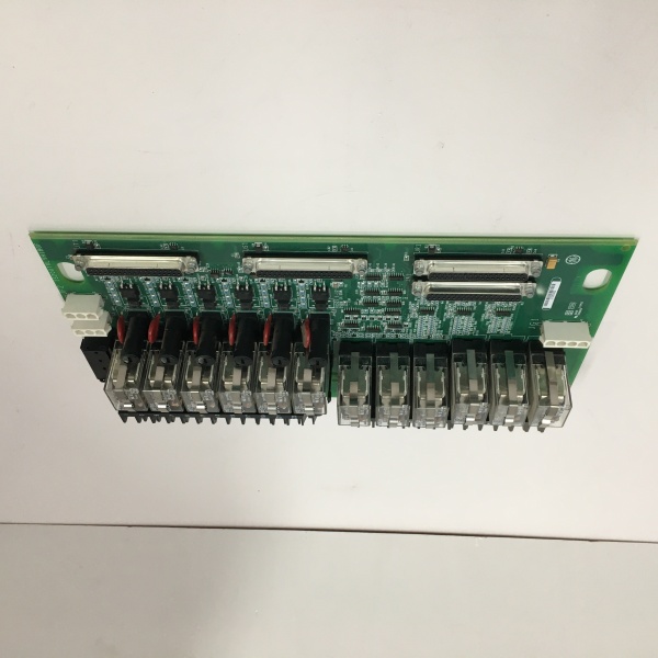
The is a passive TCAT (Core Analog Terminal) board, forming the field-facing interface for analog signals in a Mark VIe rack. It doesn’t run code; it sits on a DIN rail (metal base with plastic carrier) and bridges the gap between sensors and the active PCAA I/O packs.
Physically, it hosts 120 pluggable Euro-style terminals divided into groups (48, 24, 48). Field wires (LVDTs from fuel valves, Seismic sensors on bearings, 4-20mA transmitters for pressure) land here. The board uses high-reliability passive circuits to “fan out” these signals: in a TMR (Triple Modular Redundant) setup, the same field signal is routed via 68-pin cables to three separate PCAA packs (R, S, T). This ensures a wiring fault on one leg doesn’t kill the vote.
It draws 28V DC and 15V DC from the connected PCAA module(s) to power onboard regulators (for 24V transmitter excitation) and signal conditioning (low-pass filters for seismic). The “H1A” revision includes specific trace routing for noise isolation. It operates at Level 1 (Field Termination), ensuring that high-impedance analog signals are conditioned close to the source before hitting the digital IONet backbone.
IS200TRLYH1B
Core Technical Specifications
- Input Channels: 12 Seismic, 12 LVDT (Position), 24 4-20mA, 2 Magnetic Pulse Rate
- Output Channels: 3 Voted 4-20mA (Hardware voted via PCAA logic)
- Power I/O: 28 V DC & 15V DC (Sourced FROM PCAA pack via 68-pin)
- Excitation Output: 12x 24V DC @ 25mA (For 4-20mA loops, reg’d on-board)
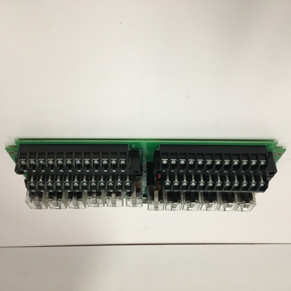
- Terminals: 120 Pluggable Euro-Style (Groups: 48 / 24 / 48)
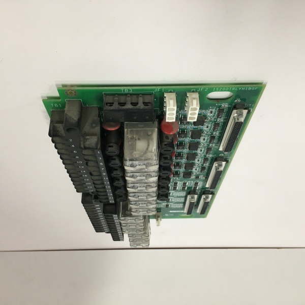
- I/O Pack I/F: 2x 68-pin Connectors (PR1/PS1/PT1 & PR2/PS2/PT2 to PCAA)
- Cable ID: Electronic ID chips (PCAA verifies correct TCAT is connected)
- Isolation: Channel-to-Channel (Via PCAA Optos), Passive Trace Isolation on TCAT
- Jumpers: Config per channel (Source/Sink, 2-wire/3-wire LVDT, Return settings)
- Mounting: DIN Rail (TS-35) via Metal Carrier (Insulating plastic shim)
- Environmental: -30°C to +65°C, Conformal Coated
Customer Value & Operational Benefits
Centralized Analog Management
Instead of scattering analog terminations across multiple small boards, the TCAT consolidates LVDT, Seismic, and 4-20mA into one high-density block. This puts all your turbine “health” signals (vibration, valve position, pressure) in one physical location. During a trip event, you can trend correlated data (LVDT position vs. Seismic spike) without tracing wires across three different terminal strips, slashing root cause analysis time from hours to minutes.
TMR Wiring Integrity
The passive fan-out design means you land the field wire once on the TCAT, and the board splits it to R, S, and T PCAA packs. If the “R” core has a 68-pin cable fault, the “S” and “T” paths remain live because the TCAT’s PCB traces are isolated per leg. This maintains your 2oo3 vote even with a loose backplane cable, preventing a spurious turbine trip during high-vibration events (e.g., startup).
Hot-Swap Field Wiring
Because the terminals are pluggable Euro-blocks, you can unplug the entire field wire harness from the TCAT while the turbine is running (carefully, for non-critical loops) to swap a faulty board, or simply to re-terminate. You don’t unscrew 48 individual wires one-by-one. This cuts MTTR (Mean Time To Repair) by 70% during forced outages.
Field Engineer’s Notes (From the Trenches)
The TCAT is passive, but it’s the #1 point of failure for analog drift in my experience. The 68-pin ribbon cables (connecting to PCAA) are the weak link. Turbine vibration works these cables loose over 12-18 months.
My Rule: During annual outage, unplug and re-seat both ends of the 68-pin cables (PR1/PR2 etc.). Check the female headers on the TCAT for corrosion—the 24V excitation traces are tiny; a speck of dust bridges them, blowing the PCAA’s regulator.
Also, Jumper Settings are permanent documentation. The LVDT inputs (Pots 1-12) have jumpers for “Excitation Return.” If you swap a TCAT in the field and guess the jumper positions (2-wire vs 3-wire LVDT), your valve position loop will hunt or rail. Photograph the old board’s jumpers before pulling it. And for God’s sake, don’t use “No-Clean” flux when soldering field wires to the Euro-blocks; the residue is slightly conductive and will cause phantom 4-20mA readings (ghosting) on adjacent channels in high-humidity plants.
IS200TRLYH1B
Real-World Applications
- Gas Turbine Fuel Stroke Control: The TCAT hosts the LVDT inputs (12 channels) from the Fuel Stroke Reference (FSR) and Gas Control Valve (GCV) actuators. It fans these position signals to three PCAA packs. If a squirrel chews the “R” core’s 68-pin cable, S and T still vote “Valve Closed,” preventing a false overspeed trip.
- Bearing Seismic Monitoring: Terminating 12 Seismic (Accelerometer) inputs from the #1, #2, and #3 bearings. The TCAT’s passive low-pass filtering cleans the raw mV signals before the PCAA digitizes them for vibration analysis (1X/2X/Subsynchronous).
High-Frequency Troubleshooting FAQ
Q: My PCAA pack shows “Input Failure” or “Open Circuit” on LVDT Ch 3, but the wiring at the valve is good. What’s wrong?
A: Check the TCAT Jumper Configuration for that channel (Jumper block near Ch 3). If the LVDT is 3-wire (Separate Excitation Return) but the jumper is set for 2-wire (Common Return), the loop won’t close and the PCAA sees infinite impedance. Also, wiggle the 68-pin connector (PR1/PS1) at the TCAT; a micro-crack in the PCB trace at the connector foot can cause intermittent contact that a multimeter misses but a vibration transient catches.
A: Yes. Connect your single PCAA to the PR1/PS1/PT1 headers (Primary). Leave PR2/PS2/PT2 unconnected. In ToolboxST, configure the PCAA for “Simplex” mode. The TCAT hardware supports Simplex, Dual, or TMR; it’s the I/O Pack’s software config that dictates the logic. Do not mix R/S/T cables if you only have one pack—leave the unused headers capped.
Q: The 4-20mA inputs read 0mA, but I have 24V at the transmitter. Is the TCAT bad?
A: Verify the 24V Excitation Output from the TCAT. The TCAT derives 24V from the PCAA’s 28V supply via an on-board regulator. If the “24V Out” terminals on the TCAT read 0V (should be ~24V), check the 68-pin cable (Pin integrity) from the PCAA. If the PCAA’s 28V rail is good but TCAT output is 0V, the TCAT’s PTC fuse (resettable) on the excitation reg may have tripped from a field short. Let it cool/power cycle, or check for a dead short on the field loop (e.g., 4-20mA + and – tied together).
Please note: The listed price is not the actual final price. It is for reference only and is subject to appropriate negotiation based on current market conditions, quantity, and availability.


