
Description
Hard-Numbers: Technical Specifications
- Input Channels: 8 × RTD (Pt100, 100Ω @ 0°C)
- Wiring Config: 2-wire, 3-wire, 4-wire selectable
- Temperature Range: -200°C to +850°C
- Accuracy: ±0.1°C
- Isolation Rating: 2500 VAC field-to-backplane
- Power Draw: 5.4 W max @ 24 VDC
- Operating Temp: -40°C to +70°C
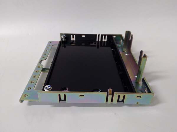
- Mounting: 35mm standard DIN rail
- Dimensions: 264 × 167 × 55 mm (10.4 × 6.6 × 2.2 in)
- Weight: 1.2 kg (2.65 lb)
- Certifications: UL, CE, Class I Div 2, ATEX Zone 2
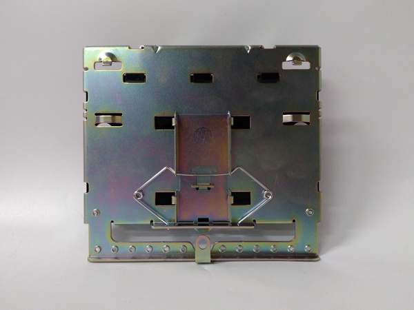
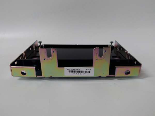
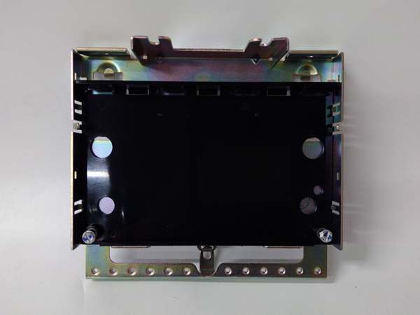
IS230STCIH6A
The Real-World Problem It Solves
Turbine enclosures are noisy. Long RTD runs suffer lead resistance and ground-loop errors. Unconditioned inputs corrupt low-level temperature measurements, risking false trips. provides galvanic isolation and precision termination to stabilize RTD signals for Mark VIe controllers.
Where you’ll typically find it:
- Gas/steam turbine bearing temperature acquisition
- Compressor casing and shaft temperature surveillance
- Lube oil and hydraulic fluid temperature monitoring
Bottom line: ensures reliable temperature data for turbine protection and efficiency.
Hardware Architecture & Under-the-Hood Logic
is a passive termination board with no on-board microcontroller. It routes RTD signals to external PRTD/VRTD I/O processors for signal conditioning.
- RTD sensors connect to euro-block terminals; wiring mode set via external configuration.
- Termination board routes sensor signals to dedicated backplane connectors.
- PRTD/VRTD processors apply constant-current excitation and measure RTD resistance.
- Isolated amplifiers condition signals before 16-bit ADC conversion.
- Processed temperature data transmits over IONet to the main controller.
- Front LEDs indicate channel status and fault conditions.
Field Service Pitfalls: What Rookies Get Wrong
Miswiring Euro-Block TerminalsTechnicians reverse RTD lead connections, causing offset errors or open-circuit faults.
- Field Rule: Label RTD leads (Power, Sense, Return) and match to terminal blocks per wiring diagram.
Missing Shield GroundingUnshielded RTD cables pick up EMI from VFDs, creating 2–5°C measurement noise.
- Quick Fix: Use shielded twisted-pair cable; ground shield only at the end.
Overlooking Mechanical ClearanceDIN-rail stacking blocks airflow. Elevated temps cause intermittent signal drift.
- Field Rule: Leave 50mm vertical clearance above/below the module for airflow.
IS230STCIH6A
Commercial Availability & Pricing Note
Please note: The listed price is for reference only and is not binding. Final pricing and terms are subject to negotiation based on current market conditions and availability.


