
Description
Hard-Numbers: Technical Specifications
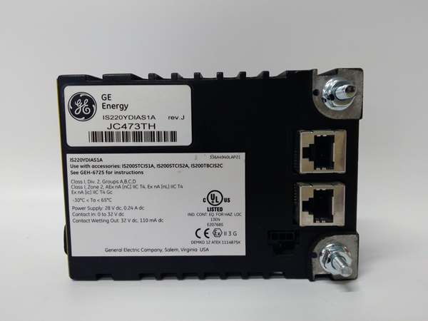
- Communication: Dual redundant IONet 10/100Mbps Ethernet (RJ45)
- Speed Inputs: 4× magnetic speed sensors (2–20,000 Hz)
- Voltage Inputs: Bus/generator voltage, shaft voltage/current inputs
- Flame Inputs: 8× flame detector pulse inputs (≥2.5V = logic high)
- Trip Outputs: 2× solid-state primary trip relays (via TRPA terminal board)
- Isolation: 2500 VAC RMS field-to-backplane isolation
- Power Requirements: 28 VDC, 10 W max
- Operating Temp: -40°C to +60°C (industrial)
- Safety Rating: IEC 61508 SIL 3 capable
- Certifications: UL, CE, ATEX Zone 2, Class I Div 2
- Compatible Terminals: TTURS1C, TRPAS1A, TRPAS2A, TRPGS1B, TRPGS2B
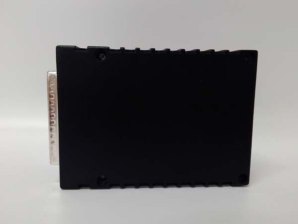
- Dimensions: 138 × 86 × 56 mm
- Weight: 0.9 kg (2 lbs)
- Firmware: ToolboxST configurable
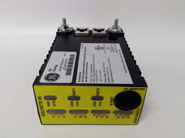
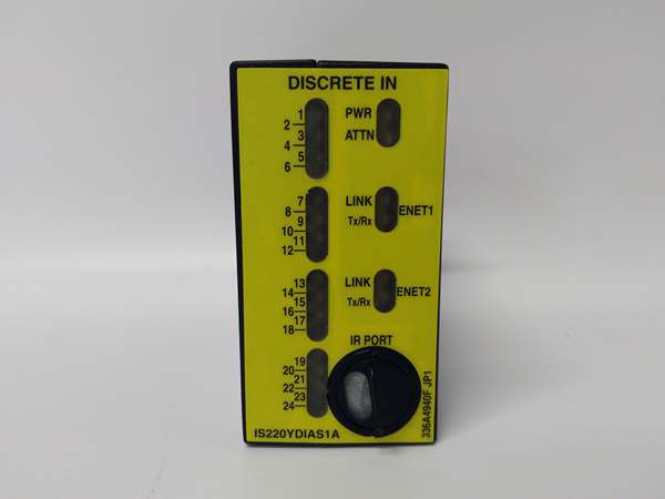
GE IS220YDIAS1A
The Real-World Problem It Solves
Turbine protection relies on accurate, fail-safe sensing of speed, voltage, and flame. Signal noise, ground loops, or lack of isolation cause false trips or missed faults—leading to catastrophic failure or unplanned downtime. provides fully isolated, safety-rated signal conditioning for all critical turbine inputs, ensuring reliable primary protection.Where you’ll typically find it:
- Gas turbine magnetic speed pickup (MPU) interface
- Generator/bus voltage and shaft voltage monitoring
- Combustion flame sensor input conditioning
- Primary ESD (Emergency Shutdown) trip logicBottom line: is the first line of defense for turbine overspeed, overvoltage, and loss-of-flame protection.
Hardware Architecture & Under-the-Hood Logic
operates as a dedicated safety I/O hub with isolated signal paths:
- Field signals (speed/voltage/flame) feed through isolated front-end circuits.
- On-board processor digitizes and validates inputs with continuous diagnostics.
- Redundant IONet transmits data to the safety controller.
- Internal logic monitors for over-speed, over-voltage, or flame-out conditions.
- Triggers fail-safe solid-state trip outputs via terminal board relays.
- Front-panel LEDs indicate channel status, COMM, RUN, and TRIP states.
Field Service Pitfalls: What Rookies Get Wrong
Shield Ground MiswiringGrounding both ends of speed sensor shields creates ground loops. Induces noise, corrupts speed signals, causes false trips.
- Field Rule: Single-point ground shield at TTURS/TRPA terminal board only; float sensor end.
Incorrect Speed Sensor GapSetting MPU gap too small/large degrades signal quality. Results in erratic speed readings or dropout.
- Quick Fix: Set gap to 0.8–1.2 mm (0.03–0.05 in); verify signal amplitude ≥10Vpp.
Non-Isolated Power SharingPowering YTUR from non-safety, noisy power supplies. Causes cross-talk and safety system faults.
- Field Rule: Use dedicated 28 VDC safety-rated power; isolate from control system power.
Mixed Terminal Board ConfigsUsing incompatible terminal boards breaks isolation/safety. Disables trip relay functionality.
- Field Rule: Use only TTURS1C or TRPAS1A/B boards; follow GE schematic GEH-6721P.
Commercial Availability & Pricing Note
Please note: The listed price is for reference only and is not binding. Final pricing and terms are subject to negotiation based on current market conditions and availability.


