
Description
Hard-Numbers: Technical Specifications
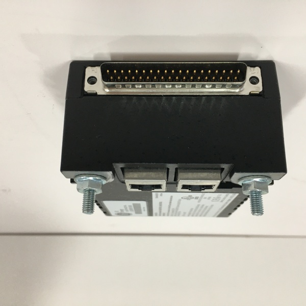
- Protocol Support: Dual IONet 10/100Mbps Ethernet (RJ45)
- Output Channels: 12 Form C relay outputs
- Contact Rating: 2A @ 30VDC / 1A @ 120VAC
- Isolation Rating: 2500 VAC RMS field-to-backplane
- Power Draw: 9 W max @ 28 VDC
- Operating Temperature: -40°C to +70°C
- Response Time: ~6 ms (command to output)
- Diagnostics: 12 channel LEDs, fuse/coil/contact feedback
- Terminal Board Compatibility: TRLYS1B, TRLYS1D, TRLYS1F
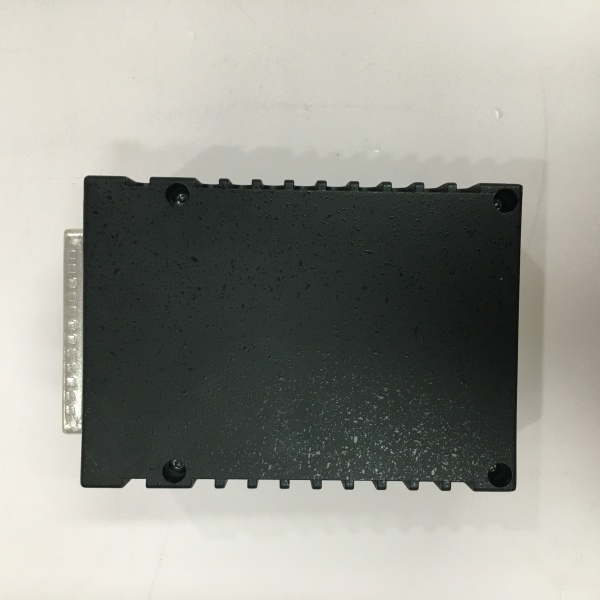
- Dimensions: 138 x 86 x 56 mm
- Weight: 0.9 kg (2 lbs)
- Certifications: UL, CE, ATEX Zone 2, Class I Div 2
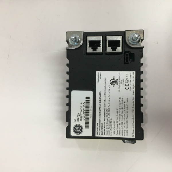
GE IS220YAICS1A
The Real-World Problem It Solves
Unmonitored outputs lead to undetected open circuits or stuck relays in turbine control. Missing a trip command causes catastrophic equipment damage and extended downtime. provides full loop verification to ensure output commands reach field devices.
Where you’ll typically find it:
- Gas/steam turbine fuel stop solenoid control
- Steam bypass valve and inlet valve actuation
- Turbine supervisory and permissive interlock circuits
Bottom line: eliminates “command executed” blind spots in critical output loops.
Hardware Architecture & Under-the-Hood Logic
combines a dedicated processor with isolated relay drivers. Continuous feedback loops validate every output state against the commanded position.
- Redundant IONet receives output commands from the controller.
- On-board processor checks command integrity and redundancy vote.
- Dual drive circuits energize the selected relay coil.
- Opto-isolated feedback reads coil current and contact state.
- Processor compares commanded state vs. actual feedback.
- Mismatch triggers fault alarm and SOE event logging.
- 12 yellow front-panel LEDs indicate active output status.
Field Service Pitfalls: What Rookies Get Wrong
Inductive Load Spike DamageDirectly driving solenoids without suppression causes voltage spikes. Destroys relay contacts and damages on-board drive circuits.
- Field Rule: Install flyback diodes (DC) or RC snubbers (AC) across all inductive loads.
Fuse Status IgnoranceDisregarding the 6-channel fuse monitoring. Blown fuses cut output power without obvious alarm.
- Quick Fix: Configure system to alarm on fuse faults; verify fuses rated for 2A per channel.
Mixed Terminal Board WiringUsing non-TRLYS terminal boards breaks isolation and monitoring. Results in unreliable feedback and safety faults.
- Field Rule: Only use TRLYS1B/D/F terminal boards; match wiring to GE schematic GEI-100863.
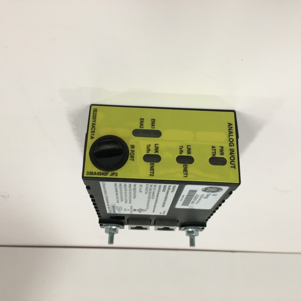
GE IS220YAICS1A
Commercial Availability & Pricing Note
Please note: The listed price is for reference only and is not binding. Final pricing and terms are subject to negotiation based on current market conditions and availability.


