
Description
Hard-Numbers: Technical Specifications
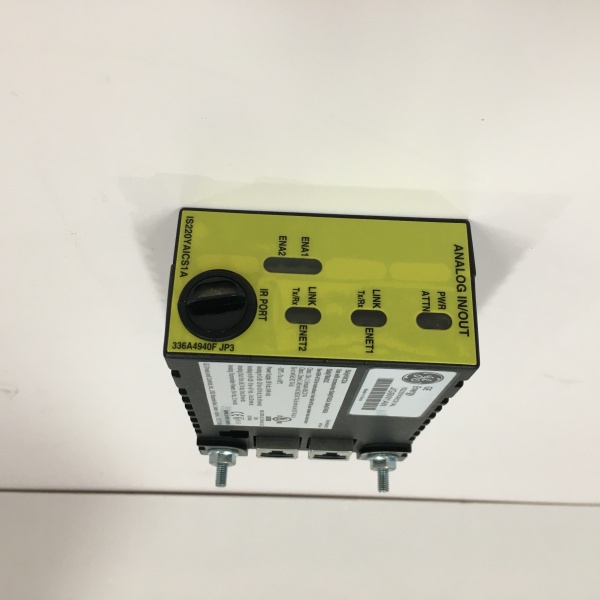
- Protocol Support: IONet 10/100Mbps Ethernet
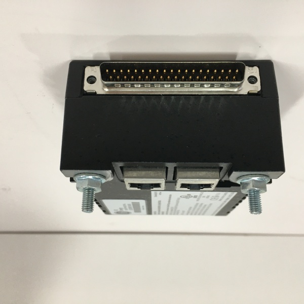
- Port Count: 2× RJ45, 1× DC-62 field connector
- Channel Count: 8×AI, 4×AO, 8×DI, 4×DO
- Isolation Rating: 2500 VAC RMS field-to-backplane
- Resolution: 16-bit for analog channels
- Power Draw: 9.5 W max @ 24 VDC
- Operating Temperature: -30°C to +65°C
- Common-Mode Rejection: 120 dB @ 50/60 Hz
- Input Voltage: 18–36 VDC
- Hazardous Rating: Class I Div 2, Zone 2
- Weight: 0.75 kg
- Dimensions: 158.75 × 107.95 × 30 mm
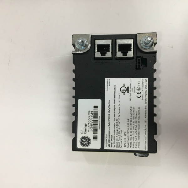
GE IS220YAICS1A
The Real-World Problem It Solves
Plants waste cabinet space and engineering hours installing separate analog and digital I/O cards. Extra modules mean more wiring, more failure points, and larger spare parts inventories. consolidates all common I/O types into one module, reducing hardware count and simplifying system design.
Where you’ll typically find it:
- Turbine lube oil, cooling, and auxiliary system control
- Feedwater and flow control loops with combined analog and discrete signals
- Compressor station auxiliary monitoring and interlock circuits
Bottom line: cuts cabinet density and installation time while maintaining full signal isolation.
Hardware Architecture & Under-the-Hood Logic
uses an on-board microcontroller and fully isolated channel circuitry. It processes signals locally before sending data over IONet to the main controller.
- Field signals terminate at the DC-62 connector to a STCIS terminal block.
- Analog and discrete inputs pass through galvanic isolation barriers.
- On-board processor digitizes AI signals and reads DI states.
- Control outputs are calculated and sent to AO and DO drivers.
- Data is transmitted to the UCS controller via redundant IONet.
- Self-diagnostics detect open circuits, short circuits, and over-range conditions.
- Module configuration loads automatically from the controller on power-up.
Field Service Pitfalls: What Rookies Get Wrong
Mixed Signal GroundingRookies share analog and discrete grounds in one bundle. This introduces noise that drifts 4–20mA readings and causes false DI triggers.
- Field Rule: Route analog and discrete wiring in separate trays; use single-point grounding at the terminal block.
Overloaded DO ChannelsTechs drive high-current solenoids directly from DO outputs. This burns internal drivers and results in stuck outputs.
- Quick Fix: Use external interposing relays for any load exceeding 100mA; never drive field devices directly.
Incorrect Shield TerminationShields grounded at both ends create ground loops that corrupt low-level analog signals. Readings become unstable and untrustworthy.
- Field Rule: Terminate cable shields only at the STCIS terminal board; leave the field end floating.
Commercial Availability & Pricing Note
Please note: The listed price is for reference only and is not binding. Final pricing and terms are subject to negotiation based on current market conditions and availability.


