

Description
Hard-Numbers: Technical Specifications
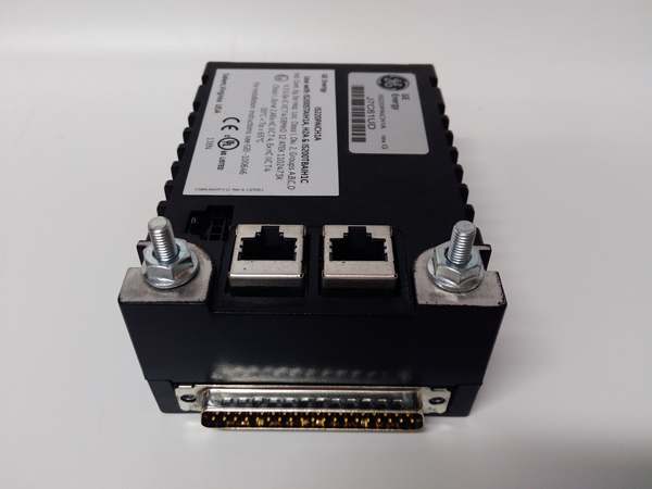
- Protocol Support: Redundant IONet 10/100Mbps Ethernet
- Port Count: 2× RJ45, 1× DC-62 field connector
- Speed Inputs: 4× passive magnetic speed channels
- Isolation Rating: 2500 VAC RMS field-to-backplane
- Processor: On-board CPU with 16MB SDRAM, 32MB Flash
- Power Requirements: 24 VDC, 8.5W max draw
- Operating Temperature: -30°C to +65°C
- Common-Mode Rejection: 120 dB @ 50/60 Hz
- Hazardous Rating: Class I Div 2, Zone 2, ATEX/IECEx
- Weight: 0.60 kg
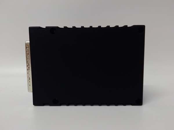
- Dimensions: 158.75 × 107.95 × 30 mm
- Firmware: Auto-reconfigurable from controller
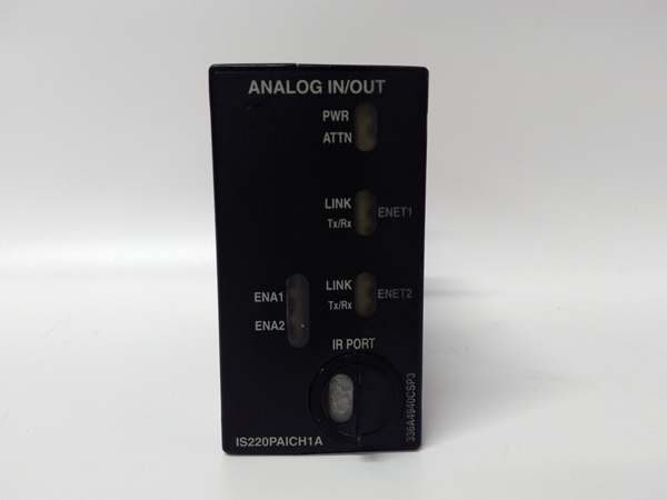
IS220PAICH1A
The Real-World Problem It Solves
Standard I/O modules lack dedicated, fault-tolerant logic for turbine safety trips. This forces reliance on the main controller, creating a single point of failure for overspeed and overtemperature shutdowns. offloads critical trip functions to dedicated hardware, ensuring failsafe operation independent of the main control processor.
Where you’ll typically find it:
- Gas turbine primary overspeed protection systems
- Steam turbine emergency shutdown (ESD) loops
- Compressor train critical speed monitoring and trip logic
Bottom line: provides hardware-enforced safety separation between control and trip functions to meet API and IEC 61508 requirements.
Hardware Architecture & Under-the-Hood Logic
operates as a standalone safety controller with its own processor and isolated signal paths. It does not depend on the main Mark VIe controller for trip execution.
- Magnetic speed signals feed into 4 isolated input channels.
- On-board CPU independently calculates rotor speed and acceleration.
- Internal trip logic compares readings to preconfigured setpoints.
- Dedicated relay outputs initiate turbine shutdown when thresholds are breached.
- Dual Ethernet ports communicate status to the main controller.
- Built-in diagnostics monitor channel health and internal integrity.
- Auto-reconfiguration loads firmware and trip settings from the controller on power-up.
IS220PAICH1A
Field Service Pitfalls: What Rookies Get Wrong
Speed Sensor Wiring Polarity ReversedReversing coil wires causes missing or erratic speed pulses, leading to failed trip tests and potential overspeed conditions.
- Field Rule: Verify phase orientation with a handheld calibrator before energizing; mark correct polarity at the terminal block.
Inadequate Signal ShieldingUnshielded cables pick up VFD and exciter noise, corrupting low-level speed signals and causing false trips.
- Quick Fix: Use twisted-pair, foil-shielded cable; ground shield only at the TTURH1C terminal board.
Improper Terminal Board TorqueLoose DC-62 connections create intermittent speed signal loss, resulting in nuisance trips during vibration or temperature swings.
- Field Rule: Torque all field terminal screws to 0.5 N·m (4.4 lb·in); re-torque after 24 hours of operation.
Commercial Availability & Pricing Note
Please note: The listed price is for reference only and is not binding. Final pricing and terms are subject to negotiation based on current market conditions and availability.


