

Description
Hard-Numbers: Technical Specifications
- Number of Channels: 2 independent servo valve channels
- Valve Type: Electro-hydraulic servo valve (2-coil differential or single-coil)
- Output Current Range: 0-40 mA per coil, ±20 mA differential
- Current Resolution: 12-bit (0.01 mA step size)
- Current Loop Update Rate: 1 kHz per channel
- Coil Resistance: 10-100 Ω typical (auto-sensing for common valve types)
- Coil Inductance: 0.1-1.0 H typical
- Output Voltage Compliance: ±24 VDC max per coil
- Position Feedback: LVDT (Linear Variable Differential Transformer) or 4-20 mA
- Feedback Resolution: 14-bit LVDT (0.01% full scale)
- Isolation: 1500V RMS between valve outputs and backplane
- Module Power Draw: 3.0A @ 5VDC from backplane
- Backplane Current: 5V: 3.0A max
- Operating Temperature: -20°C to 70°C (-4°F to 158°F)
- Storage Temperature: -40°C to 85°C (-40°F to 185°F)
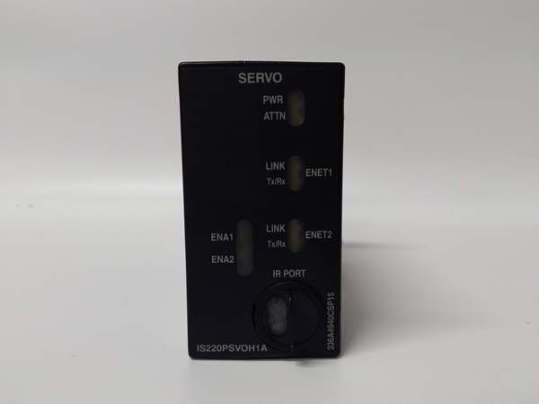
- LED Indicators: PWR, OK, FAULT, COIL A, COIL B, POS (position feedback status)
- Cooling: Forced air (requires Mark VIe backplane cooling)
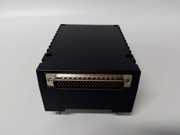
- Field Termination: Standard 36-pin terminal block (GE part number IS200PSCAH1B)
- Module Slot: Mark VIe I/O backplane (any slot in control rack)
- Communication: Backplane via TCP/IP (embedded SVO processor)
- Firmware Version: Compatible with Mark VIe v6.0 and later
- Fault Response: Fail-safe valve closure on fault (configurable spring-return mode)

IS220PSVOH1A
The Real-World Problem It Solves
Servo valves need precise current control for accurate positioning. The IS220PSVOH1A delivers dual-channel servo valve driving with 1 kHz current loop update rate and built-in position feedback, ensuring your fuel valves and governor valves respond accurately to load changes.
Where you’ll typically find it:
- Gas turbine fuel valve control systems (multiple fuel valves)
- Steam turbine governor valve control racks
- Compressor anti-surge valve actuation
Bottom line: It gives you dual-channel servo valve driving with integrated position feedback for precise valve control.
Hardware Architecture & Under-the-Hood Logic
The IS220PSVOH1A is a dedicated servo output module for Mark VIe turbine control racks. Each of the 2 channels has dedicated current output stage, DAC (Digital-to-Analog Converter), output driver, and feedback processing circuitry. The module supports dual-coil differential servo valves or single-coil configurations. Position feedback is processed from LVDT or 4-20 mA transmitters, providing closed-loop valve position control. An embedded ARM processor manages channel configuration, current loop control, fault detection, and backplane communication. Output current data is received from the main controller via backplane TCP/IP at 1 kHz update rate. The module includes adaptive filtering for hydraulic vibration and resonance rejection, reducing valve dither and improving positioning accuracy. Fault detection monitors coil open/short, position feedback loss, and watchdog timeout. On fault detection, the module drives valves to safe position (typically closed) and reports the fault to the main controller.
Internal signal flow:
- Valve position command from main controller arrives via backplane TCP/IP
- Embedded processor calculates required coil currents based on valve characterization
- Position feedback (LVDT or 4-20 mA) provides actual valve position
- Position error calculated and fed to current loop controller
- Current loop controller generates PWM duty cycle for each coil
- DAC converts PWM command to analog current command
- Output drivers amplify to produce 0-40 mA current per coil
- Hall effect current sensors measure actual coil currents
- Current feedback compared to command; error drives PI controller
- Output currents drive servo valve coils to achieve commanded position
- Adaptive filter suppresses hydraulic resonance and vibration
- Fault detection circuits monitor coils and position feedback
- On fault detection, failsafe logic drives coils to safe position
IS220PSVOH1A
Field Service Pitfalls: What Rookies Get Wrong
Incorrect LVDT calibration causes position errorThe LVDT provides valve position feedback. I’ve seen technicians skip calibration, resulting in position errors up to 10% and unstable valve response.
- Field Rule: Perform LVDT calibration after any mechanical work or valve replacement. Stroke the valve between 0% and 100% while recording LVDT output. Enter calibration points (0%, 50%, 100%) into Mark VIe module configuration. Verify position accuracy at multiple points during commissioning. Document calibration values in your maintenance log.
Mismatching coil resistance leads to oscillationEach servo valve has specific coil parameters. I’ve seen technicians install a new valve without updating coil resistance, causing the current loop to become unstable and the valve to oscillate.
- Field Rule: Always measure coil resistance with a multimeter before connecting. Record resistance values and enter them into the Mark VIe valve configuration. Perform autotune after any valve replacement to calibrate the current loop. Document coil resistance values per channel in your asset management system.
Improper grounding of LVDT shield causes noise pickupLVDT cables run long distances through high-noise environments. I’ve seen technicians connect the shield at both ends, creating ground loops and 60 Hz noise that corrupts position feedback.
- Field Rule: Use shielded twisted pair cable for LVDT wiring. Terminate the shield at the module end only—never at both ends. Maintain shield continuity throughout the run and use proper shield clamp connectors. If noise persists, consider using differential LVDT amplifiers or remote signal conditioning. Measure LVDT output noise—if 60 Hz > 5% of signal, check grounding.
Overlooking failsafe testing leads to unexpected shutdownsThe failsafe response is critical for turbine safety. I’ve seen plants trip because failsafe mode wasn’t tested during commissioning, and on a fault, the valve drove to the wrong position.
- Field Rule: Test failsafe response during commissioning and annually thereafter. Simulate a fault by disconnecting position feedback or a coil wire. Verify the valve moves to the safe position (closed for fuel valves, open for governor valves). Document failsafe direction and timing. Configure the module to trip the turbine on failsafe if required by your application.
Leaving channels unpowered during service causes undefined behaviorServo valves with no current applied float to spring-return position. I’ve seen technicians commission axes without powering coil current, causing valves to drift to unexpected positions and trigger safety trips.
- Field Rule: Always energize coil current before commissioning servo axes. Verify valve moves to commanded position when current is applied. If a valve must be disabled for service, use the module’s “disable channel” function in Mark VIe software—this drives the valve to a known safe position. Document disabled channel status in your maintenance procedure.
Not monitoring coil temperature leads to insulation failureServo valve coils generate heat during continuous operation. I’ve seen technicians ignore coil temperature warnings, resulting in coil short circuits and valve replacement.
- Field Rule: Monitor coil resistance for temperature changes. A 10% increase in resistance indicates coil overheating (typical for Class H insulation at 180°C). Reduce coil current if possible, or check hydraulic oil temperature. Install an external temperature sensor if available for high-duty applications. Record coil resistance trends during maintenance inspections.
Commercial Availability & Pricing Note
Please note: The listed price is for reference only and is not binding. Final pricing and terms are subject to negotiation based to current market conditions and availability.


